


5-29
SRW-5000/5500
CL guide rail
B3
x
12
B3
x
12
Boss
(Center of the
slotted hole)
Slotted
hole
• Top view
AT head assembly
Harness
Boss
Boss
Slotted hole
PSW3
x
8
PSW3
x
8
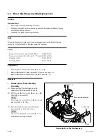
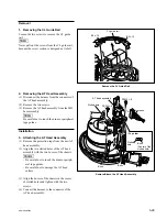
Removal
1. Removing the CL Guide Rail
Loosen the two screws to remove the CL guide
rail.
n
Never pull out the screws from the CL guide rail,
because the screw section is designed not to fall.
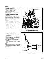
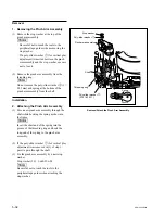
2. Removing the AT Head Assembly
(1) Disconnect the harness from the connector of
the AT head assembly.
(2) Remove the two screws.
(3) Remove the AT head assembly from the MD
base assembly.
n
Be careful not to touch the drum or peripheral
tape guides.
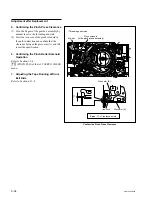
Installation
3. Attaching the AT Head Assembly
(1) Remove the protection tape from the new AT
head assembly.
(2) Align the two slotted holes of the AT head
assembly with the two bosses of the chassis.
m
.
Be careful not to touch the drum or periph-
eral tape guides.
.
Be careful not to damage the AT head
surface.
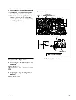
(3) Align the bosses of the chassis in the center
of slotted holes and tighten with the two
screws.
(4) Connect the harness to the connector of the
AT head assembly.
Remove the CL Guide Rail
Remove/Attach the AT Head Assembly