


6-8
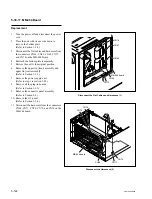
SRW-5000/5500
A
B
C
D
E
F
G
H
J
K
L
M
N
S802
P
1
2
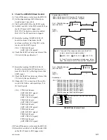
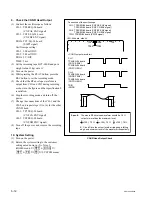
Waveforms appear with no lacking.
Uniform waveforms without variation.
Spec.3 :
(OK)
.
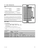
Alignment tape : HR2-1B (00:00 to 20:00)
S802-1/SS-95 board : OFF (Tracking VR : Disabled)
CH-2 : TP5/EQ-94 board
(SWP5)
CH-1 : TP52/EQ-94 board
(CNF CG ENV)
<SS-95 board, side A>
A
B
C
D
E
F
G
H
J
K
L
M
N
P
1
2
TP52
TP5
<EQ-94 board, side A>
CH-1 : TP52/EQ-94 board (CNF CG ENV signal)
CH-2 : TP5/EQ-94 board (SWP5 signal)
TRIG : CH-2
.
Connection of the oscilloscope
.
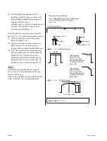
In the case of the drum entrance side is NG (Example) :
.
In the case of the drum exit side is NG (Example) :
(NG)
(NG)
(NG)
(NG)
5. Check in the REV
x
x
x
x
x
1 Mode
(1) Set Bit-1 of the DIP switch S802 on the SS-
95 board to OFF (lower side) to fix the
tracking control.
(2) Play back the alignment tape HR2-1B (00:00
to 20:00).
(3) Set the REV
x
1 mode, and check that the RF
envelope waveform satisfies specification 3.
If the waveform at the entrance is without the
specification 3, adjust tracking at the drum
entrance. (Refer to Section 6-3.)
If the waveform at the exit is NG, adjust the
height of TG-5 before tracking adjustment.
n
Adjusting the height of TG-5
Be sure to make an adjustment within the
height where no tape curl occur at upper and
lower flanges.
If the specification is still not satisfied, adjust
tracking at the drum exit. (Refer to Section 6-
4.)