


6-12
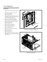
SRW-5000/5500
A
B
C
D
E
F
G
H
J
K
L
M
N
P
1
2
3
TP44
TP48
TP5
TP40
TP52
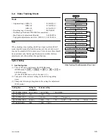
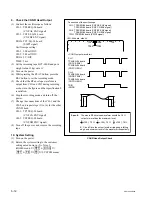
CH-1: TP44/EQ-94 board (CNF AE ENV signal)
TP52/EQ-94 board (CNF CG ENV signal)
CH-2: TP40/EQ-94 board (CNF BF ENV signal)
TP48/EQ-94 board (CNF DH ENV signal)
TRIG: TP5/EQ-94 board (SWP5 signal)
.
Connection of the oscilloscope
CH-1:
TP44/EQ-94 board
(CNF AE ENV)
TP52/EQ-94 board
(CNF CG ENV)
CH-2:
TP40/EQ-94 board
(CNF BF ENV)
TP48/EQ-94 board
(CNF DH ENV)
TRIG
(SWP5)
A
B
C
D
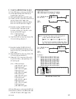
<CONFI output waveform>
<EQ-94 board, side A>
B
A
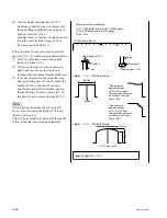
Spec.8 :
x
100
>
70 %
C
A
x
100
>
70 %
D
A
x
100
>
70 %
B, C, and D are the output levels at rising edge, falling
edge, and minimum level of the waveform, respectively.
The whole RF envelope waveform should be 70 %
output or more than the maximum level.
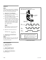
CONFI Head Output Check
9. Check the CONFI Head Output
(1) Connect the oscilloscope as follows:
CH-1: TP44/EQ-94 board
(CNF AE ENV signal)
CH-2: TP40/ EQ-94 board
(CNF BF ENV signal)
TRIG: TP5/ EQ-94 board
(SWP5 signal)
Oscilloscope setting:
CH-1: 500 mV/DIV
CH-2: 500 mV/DIV
TRIG: 5 V/DIV
TIME: 5 ms
(2) Set the recording tape BCT-40SR and put a
weight (about 1 kg) onto it.
(3) Turn on the power.
(4) While pressing the PLAY button, press the
REC button to set the recording mode.
(5) Check that the RF envelope waveform is
output from CH1 and CH2 during recording
as shown in the figure and that specification 8
is satisfied.
(6) Stop the recording mode, and turn off the
power.
(7) Change the connections of the CH-1 and the
CH-2, and repeat steps (3) to (6) for the other
CONFI head.
CH-1: TP52/EQ-94 board
(CNF CG ENV signal)
CH-2: TP48/EQ-94 board
(CNF DH ENV signal)
(8) Turn off the power, and remove the recording
tape.
10. System Setting
(1) Turn on the power.
(2) Return the system setting to the customer
setting noted down in (2) of step 1.
(HOME menu
→
[SFT]
+
[DIAG]
→
[SFT]
+
[F8]
→
[F9]
→
SYSTEM menu)