


5-61
SRW-5000/5500
5-18. Threading Ring Assembly Replacement
Outline
Replacement
1.
Removing the Video Head Cleaner Assembly
(Refer to steps 1 and 2 in Section 5-4.)
2.
Disconnecting the Flexible Board (CN220/DT-47 board)
3.
Disconnecting the Harnesses (AT head, full-erase head, CTL head)
4.
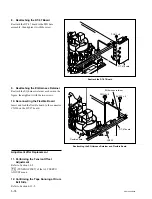
Removing the PA Guard
5.
Removing the CL Guide Rail
6.
Removing the Pinch Press Assembly (Refer to steps 1 and 2 in Section 5-9.)
7.
Removing the S Plate Assembly (Refer to steps 1 in Section 5-16-1.)
8.
Removing the S Tension Regulator Assembly
(Refer to step 1 in Section 5-19.)
9.
Removing the T Drawer Assembly (Refer to steps 1 and 2 in Section 5-21.)
10. Removing the Gear Box Assembly (Refer to steps 1 to 4 in Section 5-17.)
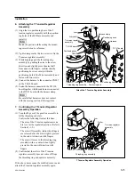
11. Removing the Ring Roller (B)
12. Removing the Threading Ring Assembly
13. Cleaning (Threading Ring Assembly, Ring Roller)
14. Attaching the Threading Ring Assembly
15. Attaching the Ring Roller (B)
16. Confirming the Threading Ring Operation
17. Reattaching the Gear Box Assembly (Refer to steps 5 and 6 in Section 5-17.)
18. Reattaching the Pinch Press Assembly (Refer to steps 3 and 4 in Section 5-9.)
19. Putting the Unit into the Unthreading End Mode
20. Reattaching the S Tension Regulator Assembly (Refer to step 2 in Section 5-19.)
21. Reattaching the S Plate Assembly (Refer to step 2 in Section 5-16-1.)
22. Reattaching the T Drawer Assembly (Refer to steps 3 to 6 in Section 5-21.)
23. Reattaching the CL Guide Rail
24. Confirming the CL Arm Assembly Operation (Refer to step 3 in Section 5-5.)
25. Reattaching the PA Guard
26. Reconnecting the Flexible Board (CN220/DT-47 Board)
27. Reconnecting the Harness (AT head, full-erase head, CTL head)
28. Reattaching the Video Head Cleaner Assembly
(Refer to steps 4 to 6 in Section 5-4.)
Adjustment after Replacement
29. Confirming the Cleaning Solenoid Operation (Refer to Section 3-3-4.)
[F6]
(CLEAN PLG) of the ALT SERVO CHECK menu
30. Performing the Tension Offset Adjustment (Refer to Section 3-4-2.)
[F4]
(TENSN OFFSET) of the ALT SERVO ADJUST menu
31. Confirming the Pinch Press Clearance (Refer to step 5 in Section 5-9.)
32. Adjusting the Tape Running (Refer to Sections 6-2 to 6-12.)
Tools
.
Cleaning cloth:
3-184-527-01
.
Cleaning fluid:
9-919-573-01