


5-107
SRW-5000/5500
BVTT3
x
6
BVTP3
x
10
PSW3
x
8
Ornamental plate spacer
Switch ornamental plate
CP-378 board
CP-377 board
Lug terminal
Connector panel
assembly
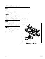
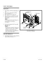
5-30-4. CP-377 Board
Replacement
1.
Turn the power off and disconnect the power
cord.
2.
Remove the connector panel assembly.
(Refer to Section 1-4.)
3.
Remove the CP-376/CP-376A board.
(Refer to Section 5-30-3.)
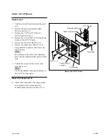
4.
Remove the screw (PSW3
x
8) fixing the lug
terminal to the CP-378 board.
5.
Remove the two screws (BVTT3
x
6).
6.
Remove the eight screws (BVTP3
x
10)
fixing the BNC connectors and remove the
CP-377 board.
n
Be careful not to loose the SW ornamental
plates and the ornamental plate spacers at this
time.
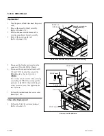
7.
Perform the removal in the reverse order
from steps 2 to 5.
n
Fix the rug terminal of the ground harness to
the CP-378 board properly.
Steps after Replacement
8.
Check if the component video output signal
and composite video output signal are
normally output. (Refer to Section 1-25-6.)
Remove the CP-377 Board