


5-76
SRW-5000/5500
C
PWH3
x
8
PWH3
x
8
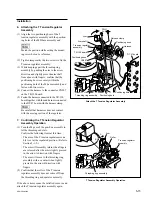
T drawer
assembly
Positioning
boss (B)
Tape top sensor
Harness
Positioning
hole (B)
Positioning hole (A)
Hook
Positioning boss (A)
Positioning boss (A)
Threading ring assembly
Harness
Lug terminal
T drawer assembly
ME wire
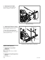
PWH3
x
8
Holes
Plate holder (T)
assembly
Wire cover
Claw
Wire holder
DT-47 board
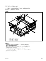
Remove the ME Wire
Remove the T Drawer Assembly
Removal
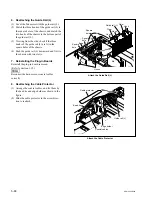
1. Removing the ME Wire
(1) Release the tip of the ME wire from the wire
holder.
(2) Remove the screw securing the lug terminal
of the ME wire.
(3) Grasp the hole of the wire cover with a pair
of pliers, press the claw on the cover in the
arrow direction, and remove the wire cover
from the plate holder (T) assembly.
(4) Remove the ME wire from the T drawer
assembly as shown in the figure.
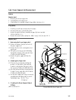
2. Removing the T Drawer Assembly
(1) Disconnect the harness from the connector of
the tape top sensor.
(2) Release the harness from the hook of the T
drawer assembly.
(3) Remove the two screws.
(4) Remove the positioning boss (A) from the
positioning hole of the MD base assembly by
lifting up the T drawer assembly.
(5) Remove the positioning boss (B) from the
positioning hole (B) while turning the T
drawer assembly in the arrow C direction.