


7-15
SRW-5000/5500
A
B
C
D
E
1
2
3
4
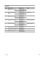
TP102
TP401
TP400
E400
TP301
TP200
TP201
E100
LV200
TP100
TP101
7-3-3. Time Code System Adjustment
Tools
.
Audio signal generator:
TEKTRONIX SG5010 or equivalent
.
Audio analyzer:
AUDIO PRECISION System One/Two
or equivalent
.
Osilloscope:
TEKTRONIX TDS3054B or equivalent
.
Time code generator: SONY BVG-1600 or equivalent
.
Time code reader:
SONY BVG-1500 or equivalent
.
Band-pass filter (1 kHz)
.
Alignment tape:
HR5-1B
.
Recording tape:
BCT-SR series
n
For this recording tape, use a blank tape erased using the
tape eraser, etc. in advence.
Preparation
1. Check the settings.
(Refer to “7-3-2. Common Preparation”.)
2. Check that the equipment has warmed up.
Before starting the adjustment, warm up the VTR and
equipment to be used through the power for 10 minutes or
more.
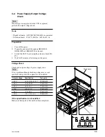
1. LTC Erasure Current Adjustment
Measuring equipment: Audio analyzer
Recording tape:
BCT-SR series
n
For this recording tape, prepare a blank tape erased using
the tape eraser, etc. in advence.
1.
Connect the audio analyzer (V rms measurement
mode) to TP201 (A-2) on the TC-104 board.
GND: E100/TC-104 (A-2)
2.
Insert the recording tape.
3.
Check the level on the audio level meter in the REC
mode.
Adj. point:
1
LV200/TC-104 (A-2)
Specification: 120 mV rms
(Note: 48.0
±
1.0 kHz)
4.
Eject the recording tape.
TC-104 Board (Side A)
CH-1
A
2. LTC PB Level Check
Measuring equipment: Oscilloscope
Alignment tape:
HR5-1B
1.
Set and connect the oscilloscope as follows:
CH-1: TP102/TC-104 (A-4), DC 100 mV/DIV
GND: E100/TC-104 (A-2)
TIME: 100
µ
s/DIV
2.
Insert the alignment tape HR5-1B.
3.
During play back the alignment tape in the PLAY
mode, check the level on the oscilloscope.
Specification: A
>
250 mV p-p
n
If specification is not satisfied, perform the “Section 6
Tape Path Alignment”.
4.
Eject the alignment tape.
Oscilloscope