


5-46
SRW-5000/5500
5-13. Reel Motor Assembly Replacement
Outline
Replacement
1.
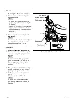
Removing the SE-606A Board
2.
Removing the ME Wire (T-side only)
3.
Removing the Shaft Holder
4.
Remove the Reel Motor Assembly
5.
Reconnecting the Flexible Board
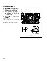
6.
Inserting the Slide Shaft
7.
Attaching the Reel Motor Assembly
8.
Attaching the ME Wire (T-side only)
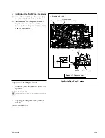
9.
Reattaching the Shaft Holder
10. Applying Grease to the Slide Shaft
11. Attaching the SE-606A Board
Adjustment after Replacement
12. Confirming the Reel Motor Operation (Refer to Section 3-3-4.)
[F5]
(S REEL MOTOR) and
[F6]
(T REEL MOTOR) of the SERVO CHECK
menu
13. Performing the Servo Adjustment (Refer to Section 3-4-2.)
[F2]
(AUTO ADJ) of the SERVO ADJUST menu
14. Adjusting the Tape Running at Drum Entrance Side (Refer to Section 6-12-1.)
Note
.
In this unit, it is not necessary to perform the traditional reel motor shaft slantness
adjustment after the reel motor assembly replacement.
.
When replacing the reel motor, be sure to perform the replacement as the reel
motor assembly. Never replace the single reel motor.
.
The parts making up the reel motor assembly is different between S side and T
side. However, how to replace the reel motor assembly is the same for both sides.
Tools
.
Torque screwdriver (12 kg
.
cm)(JB-5252):
J-6252-520-A
.
Torque screwdriver’s bit (
+
3 mm, l = 90 mm): J-6323-430-A
.
Grease (SGL-601):
7-651-000-10
.
Cleaning cloth:
3-184-527-01
.
Cleaning fluid:
9-919-573-01
Preparation
1.
Turn the power off and disconnect the power cord.
2.
Remove the upper lid (front) assembly. (Refer to Section 1-3-1.)
3.
Remove the cassette compartment. (Refer to Section 1-5.)