


6-44
SRW-5000/5500
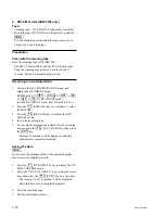
Adjustment screw
Adjustment plate
TG-10 guide
Slant guide
Adjustment
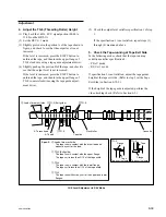
5. Adjust the TG-3 (Exit Guide) and TG-4
Height
(1) Run the S cassette tape in the PLAY and
REV
x
1 mode.
(2) Turn the height adjustment nuts of TG-3 and
TG-4 using a tape guide adjustment driver
and adjust the height of TG-3 and TG-4 so
that the specification 3 (previous page) is
satisfied.
If the specification 3 is not satisfied, adjust
height of TG-5.
When TG-3 is NG:
In the EJECT mode, rotate the upper flange
of TG-5 clockwise.
When TG-4 is NG:
In the EJECT mode, rotate the upper flange
of TG-5 counterclockwise.
(3) Perform the video tracking check. (Refer to
Sections 6-2.)
6. Recheck the Tape-running at Tape
Exit Side
Perform step 2 again.
If the specification 3 is not still satisfied, perform
the adjustment in step 5 again.
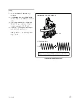
7. Adjust the Slant Guide Slantness
The T drawer assembly (RP) including the slant
guide is adjusted precisely at shipment. (The
slantness of the slant guide is also center-adjusted.)
If specification 4 (previous page) is not satisfied,
re-check the followings before adjusting the
slantness.
.
The L cassette used for checking is normal
condition.
.
The T drawer assembly is attached properly.
.
The results of other tape-running checks are
within each specification.
Adjustment
Rotate the adjustment screw of the T drawer
assembly, and adjust the position of the adjust-
ment plate so that specification 4 is satisfied.
.
If the tape is touching the upper flange of the
TG-10 guide, rotate the adjustment screw
counterclockwise.
.
If the tape is touching the lower flange of the
TG-10 guide, rotate the adjustment screw
clockwise.
Slant Guide Slantness Adjustment