


5-78
SRW-5000/5500
PWH3
x
8
Lug terminal
T drawer assembly
ME wire
Plate holder (T) assembly
ME wire
Wall
Wire cover
Wire cover
Claw
Wall
Wire holder
DT-47 board
Brake assembly
T reel table assembly
ME arm
ME wire
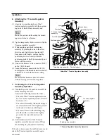
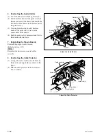
4. Attaching the ME Wire
(1) Hook the ME wire in the T drawer assembly
as shown in the figure and fix the lug termi-
nal with the screw.
Tightening torque: 78.4
x
10
_
2
N
.
m
{80.0 kgf
.
cm}
(2) Set the reel motor assembly to the S cassette
position. (Refer to Section 5-1-3.)
Next, mount the wire cover to the plate
holder (T) assembly from the top, and secure
with the claw of the wire cover.
n
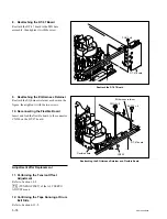
Make sure the ME wire does not protrude out
of the wall of the wire cover. (See the figure.)
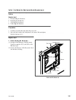
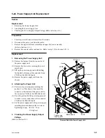
5. Confirming the ME Wire Operation
(1) Confirm that the ME arm and T real table
assembly are in mesh and the T-side reel
table rotates when lifting the loop of the tip of
the ME wire upwardly.
Perform the check each at the L cassette
position and S cassette position. (As for the
method of shifting the reel table, refer to
Section 5-1-3.)
(2) After confirmation, hang the tip of the ME
wire on the wire holder and close the wire
holder.
(3) Turn the T reel table while pressing the reel
brake assembly in the arrow direction, and
confirm that the T reel table rotates smoothly
without contacting with the ME arm.
Attach the ME Wire
Confirm the ME Wire Operation