


5-79
SRW-5000/5500
.
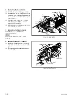
Unthreading
Pin
.
Threading
.
Threading
.
Threading end
Portion A Surface B Roller Drawer guard
At the threading state, the lower surface of the roller
does not touch with the surface B of the threading ring.
Portion C
Roller
Drawer guard
Lock arm assembly
Threading ring
Surface B
Roller
At the unthreading state, the lower surface of the roller
does not touch with the surface B of the threading ring.
Threading ring
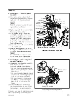
6. Confirming the T Drawer Assembly
Operation
(1) When the threading ring rotates toward the
threading end direction, check that the
portion A of the threading ring pushes the
roller of the T drawer assembly and the
drawer guard certainly. And at this time,
check that the lower surface of the roller does
not come in contact with the surface B of the
threading ring (shaded portion in the figure).
(2) When threading, check that the portion C of
the threading ring pushes certainly the roller
of the lock arm assembly, and also check that
the pin of the lock arm assembly pushes
certainly the drawer guard.
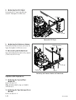
(3) When the threading ring rotates toward the
unthreading end direction, check that the
roller of the T drawer assembly moves inside
to the threading ring smoothly. And at this
time, check that the lower surface of the
roller does not come in contact with the
surface B of the threading ring (shaded
portion in the figure).
(4) When unthreading, check that the lock arm
assembly of the T drawer assembly returns
smoothly.
If the above items cannot be satisfied, remove and
attach the T drawer assembly again.
Confirm the T Drawer Assembly Operation