


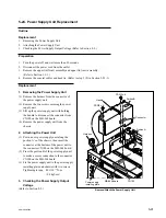


5-94
SRW-5000/5500
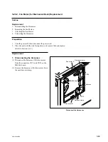
5-26. LCD Unit and Lamp Unit Replacement
5-26-1. LCD Unit Replacement
Outline
Replacement
1.
Removing the Rear Cover (Refer to step 1 in Section 5-25.)
2.
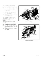
Removing the Key Panel Assembly
3.
Removing the LCD Unit
4.
Attaching the LCD Unit
5.
Reattaching the Key Panel Assembly
6.
Reattaching the Rear Cover (Refer to step 4 in Section 5-25.)
Adjustment after Replacement
7.
Color Display Indication Test (Refer to Section 3-3-3.)
[F5]
(LCD) of the PANEL CHECK menu
Note
The LCD unit as the spare part includes the lamp unit.
Preparation
1.
Turn the power off and disconnect the power cord.
2.
Remove the control panel assembly. (Refer to Section 1-6.)
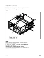
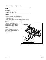
Remove/Attach the Key Panel Assembly
Removal
1. Removing the Rear Cover
Remove the rear cover.
(Refer to step 1 in Section 5-25.)
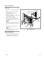
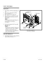
2. Removing the Key Panel Assembly
(1) Remove the MULTI CONTROL knob.
(2) Remove the eight screws and remove the key
panel assembly.
(3) Disconnect the flexible card wire from the
connector CN1 on the KY-526 board.
Key panel frame
Key panel assembly
MULTI CONTROL knob
CN1
B3
x
6
B3
x
6
KY-526 board