


5-35
SRW-5000/5500
5-9. Pinch Press Assembly Replacement
Outline
Replacement
1.
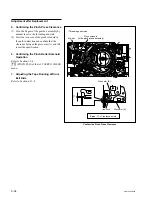
Disconnecting the Harnesses (CN216, CN231, CN233/HN-268 board)
2.
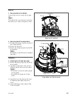
Removing the Pinch Press Assembly
3.
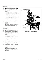
Attaching the Pinch Press Assembly
4.
Reconnecting the Harnesses (CN216, CN231, CN233/HN268 board)
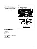
5.
Confirming the Pinch Press Clearance
Adjustment after Replacement
6.
Confirming the Pinch Roller Solenoid Operation (Refer to Section 3-3-4.)
[F3]
(PINCH PLG) of the ALT SERVO CHECK menu
7.
Adjusting the Tape Running at Drum Exit Side
Refer to Section 6-12-2.
Note
The solenoid position, etc. of the pinch press assembly is already adjusted at the
factory.
Never turn the screws other than the mounting screws when removing/attaching.
Preparation
1.
Turn the power off and disconnect the power cord.
2.
Remove the upper lid (front) assembly. (Refer to Section 1-3-1.)
3.
Remove the cassette compartment. (Refer to Section 1-5.)
4.
Open the AE-31H board. (Refer to the figure in Section 5-1-2.)