


5-114
SRW-5000/5500
CN200
CN212
CN214
CN206
CN216
CN210
CN203
CN202
CN65
CN201
CN207
CN215
CN213
CN208
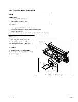
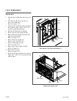
Remove the DR-508 Board
8.
Remove the two screws and remove the DR-
508 board.
9.
Remove the bracket (A) from the DR-508
board.
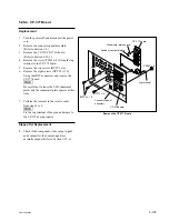
Installation
10. Attach the bracket (A) to a new DR-508
board as shown in the figure.
11. Supporting the DR-508 board with a hand,
match the two positioning bosses of the
bracket (A) to the positioning holes on the MD
base assembly and tighten with two screws.
n
Be careful not to put the harnesses between
the bracket (A) and the MD base assembly.
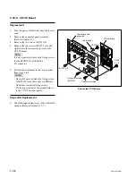
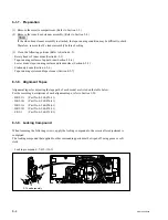
12. Connect all the harnesses and flexible boards
that have been disconnected in step 7.
13. Arrange the harnesses and fasten with wire
clamps as shown in the figure.
n
Arrange the harnesses correctly.
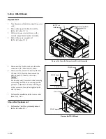
14. Turn the gear of the reel shift motor to move
the reel table at the middle position between
the S and L cassette positions.
(Refer to Section 5-1-3.)
n
Be careful not to close the DR-508 board
while the reel tables are left at the S or L
cassette position. Or the reel position sensor
may damage.
PWH
3
x
8
PWH
3
x
8
DR-508 board
Bracket (A)
Positioning holes
Positioning boss
Positioning boss
Wire clamps
Wire clamp
Flat cable
Arrange the Harnesses