


6-34
SRW-5000/5500
Adjustment
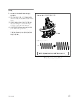
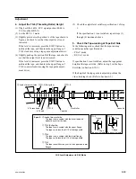
4. Adjust the AT Head Head-to-tape
Contact
(1) Loosen the two head securing screws by 1/4
to 1/2 turn.
(2) Insert a 2 mm flatbladed screwdriver into the
notch of the adjustment plate.
(3) Adjust the AT head position to maximize the
output level.
(4) Tighten the two securing screws loosened in
step (1).
Tightening torque: 19.6
x
10
_
2
N
.
m
{2 kgf
.
cm}
5. Recheck the AT Head Head-to-tape
Contact
Perform to previous step 3 in this section again.
After the adjustment
6. Check the AT Head Position
Refer to Section 6-10.
7. Check the AT Head Height
Refer to Section 6-7.
8. Check the AT Head Azimuth
Refer to Section 6-8.
AT Head Head-to-tape Contact Adjustment
Head securing screws
(PS2
x
5)
Notch
CUE
Maximize