


6-13
SRW-5000/5500
START
NG
NG
OK
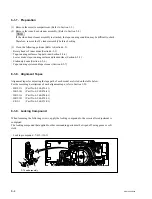
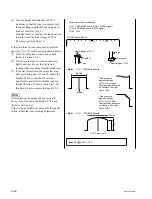
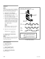
1. Adjust the Tracking at Tape Entrance Side
2. Adjust the HDCAM DT Head Contact
TG-2 Fine Adjustment
Fine Adjustment of TG-1 Height
3. Check the Tape-running at the Tape Entrance Side
4. Recheck the Video Tracking
END
6-3. Tracking Adjustment at the
Tape Entrance Side
This adjustment should be performed when the
specifications have not been satisfied in Section
6-2 (steps 4, 5, 6, and 7.)
If you start the operation from this adjustment,
perform the settings (steps 2 and 3) in Section
6-2 first.
n
In the video tracking adjustment, the RF envelope
waveform should be made flat to the entrance and
exit. However it may not be completely flat in
some cases. For such cases, there should be no
problems only that the specifications are satisfied.
Perform adjustments paying attention to the
followings:
.
Perform only the adjustment indicated.
.
Do not rotate screws other than those specified
in the adjustments.
Take note that performing adjustments other than
those required for making the RF envelope
waveform flat may result in damages such as
abnormal wear of mechanism parts and accompa-
nying deterioration of electrical characteristics.
Flow Chart of Tracking Adjustment at the Tape Entrance Side