


6-16
SRW-5000/5500
.
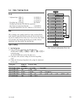
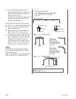
Alignment tape : HR2-1B (00:00 to 20:00)
S802-1/SS-95 board : ON (Tracking VR : Enabled)
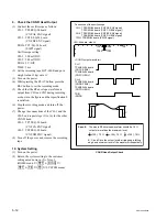
Marker
RF max
If the pressure against the
tape at TG-2 is too much,
the waveform becomes as
shown in the upper figure.
(NG)
The RF envelope waveform is flat.
Spec.11 :
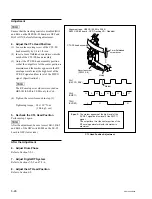
CH-1 :
TP52/EQ-94 board
A
B
C
D
E
F
G
H
J
K
L
M
N
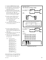
S802
RV1001 (Tracking VR)
P
1
2
<SS-95 board, side A>
A
B
C
D
E
F
G
H
J
K
L
M
N
P
1
2
TP52
TP5
<EQ-94 board, side A>
CH-1 : TP52/EQ-94 board (CNF CG ENV signal)
CH-2 : TP5/EQ-94 board (SWP5 signal)
TRIG : CH-2
.
Connection of the oscilloscope
n
Perform the following steps (9) to (16) only if the
specification 10 was not satisfied.
(9) Turn off the power, then remove the HR2-
1A.
(10)Reset Bit-3 of the DIP switch S802 on the
SS-95 board to OFF (lower side).
(11)Set the alignment tape HR2-1B and put a
weight (about 1 kg) onto it.
(12)Turn on the power, then play back the HR2-
1B (00:00 to 20:00) in the PLAY mode.
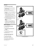
(13)Rotate the tracking VR (RV1001/SS-95
board) clockwise to set the center of the RF
envelope waveform to 80 % of the maximum
output level, then check that the waveform
satisfies the specification 11.
(14)Slightly rotate the height adjustment nut of
TG-2 a little clockwise.
(15)Check again that the waveform satisfies the
specification 11.
If specification 11 is not satisfied, perform
the adjustment (4) of step 1 and later again.
(16)Perform steps (1) to (6) again to check that
the specification 10 is satisfied. If the specifi-
cation 10 is satisfied, proceed to step (7). If
not, perform the following steps
1
to
4
.
1
Turn off the power, and remove the HR2-
1A.
2
Set the HR2-1B, and put a weight (about
1 kg) onto it.
3
Reset Bit-3 of the DIP switch S802 on
the SS-95 board to OFF (lower side).
4
Turn on the power, and perform (2) of
step 1 and later.
TG-2 Fine Adjustment