


6-18
SRW-5000/5500
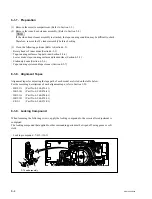
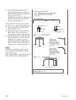
CL guide rail
B3
x
8
CL Guide Rail Removal
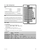
6-4. Tracking Adjustment at the
Tape Exit Side
This adjustment should be performed when the
specifications have not been satisfied in Section
6-2 (steps 4, 5, 6, and 7.)
If you start the operation from this adjustment,
perform the settings (steps 2 and 3) in Section 6-2
first.
n
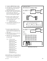
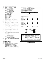
In the video tracking adjustment, the RF envelope
waveform should be made flat from the entrance
to the exit. However it may not be completely flat
in some cases. For such cases, there should be no
problems only that the specifications are satisfied.
Perform adjustments paying attention to the
following:
.
Perform only the adjustment indicated.
.
Do not rotate screws other than those specified
in the adjustments.
Take note that performing adjustments other than
those required for making the RF envelope
waveform flat may result in damages such as
abnormal wear of mechanism parts and accompa-
nying deterioration of electrical characteristics.
1. Remove the CL Guide Rail
(1) Turn off the power.
(2) Fully loosen the two screws to remove the
CL guide rail.
m
.
When removing the CL guide rail, be
careful not to damage the tape.
.
Do not pull out the screws because the
screw holes on the CL guide rail are shaped
in such a way to prevent screws from
falling.