


5-112
SRW-5000/5500
BVTT3
x
6
(with stopper)
Cassette compartment
bracket assembly
DIO-69 board
FP-131 board
HP-110 board
Portion A
Flexible card wire
DIO-69 board
CN1
CN1
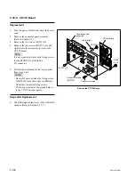
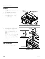
5-30-8. DIO-69 Board
Replacement
1.
Turn the power off and disconnect the power
cord.
2.
Remove the upper lid (front) assembly.
(Refer to Section 1-3-1.)
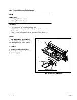
3.
Fully loosen one screw and remove the
cassette compartment bracket assembly.
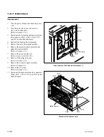
4.
Remove the power supply unit.
(Refer to Section 5-24.)
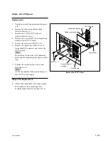
5.
Disconnect the flexble card wire from the
connector CN1 on the DIO-69 board.
6.
Disconnect the connection between the HP-
110 and FP-131 boards, then remove the
DIO-69 board in the arrow direction.
n
For recorder only, be careful when removing
or installing the DIO-69 board, support the
portion A of the HP-110 board with fingers
so that excessive force is not applied to the
HP-110 board.
7.
Perform the installation in the reverse order
from steps 2 to 6.
Steps after Replacement
8.
Perform the Tele-File system adjustment.
(Refer to Section 8-9.)
Remove the Cassette Compartment Bracket Assembly
Remove the DIO-69 Board