


5-51
SRW-5000/5500
PWH3
x
8
ME wire
Wall
Wire cover
Wire cover
Claw
Wall
Wire holder
DT-47 board
Lug terminal
T drawer assembly
ME wire
Plate holder (T) assembly
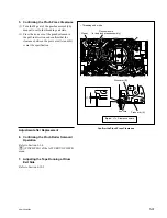
Attach the ME Wire
10. Attaching the ME Wire (T-side only)
(1) Hook the ME wire in the T drawer assembly
as shown in the figure and fix the lug termi-
nal with the screw.
Tightening torque: 78.4
x
10
_
2
N
.
m
{8.0 kgf
.
cm}
(2) Set the reel motor assembly to the S cassette
position. (Refer to Section 5-1-3.)
Next, mount the wire cover to the plate
holder (T) assembly from the top, and secure
with the claw of the wire cover.
n
Make sure the ME wire does not protrude out
of the wall of the wire cover. (See the figure.)
(3) Confirm that the ME wire moves smoothly
and the reel table rotates when the tip of the
ME wire is drawn. (Refer to (1) and (2) of
step 5 in Section 5-21.)
(4) Hang the tip of the ME wire on the wire
holder and close the wire holder.
11. Reattaching the SE-606A Board
Reattach the SE-606A board in the reverse order
of step 1.
Adjustment after Replacement
12. Confirming the Reel Motor Operation
Refer to Section 3-3-4.
[F5]
(S REEL MOTOR) and
[F6]
(T REEL
MOTOR) of the SERVO CHECK menu
13. Performing Servo Adjustment
Refer to Section 3-4-2.
[F2]
(AUTO ADJ) of the SERVO ADJUST
menu
14. Adjusting the Tape Running at Drum
Entrance Side
Refer to Section 6-12-1.