1161
Failure Diagnosis Instructions
Section 3-30
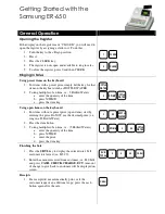
Register words R+2 through R+5 would have the following values for W51115:
The user can store an ASCII message in register words R+6 to R+10. This
message will be displayed on the Programming Device if a non-fatal error is
generated by the time monitoring function. Mark the end of the message with
the null character (00 hexadecimal).
Disabling Error Log
Entries of Non-fatal
FPD(269) Errors
(CS1-H, CJ1-H, CJ1M, or
CS1D Only)
Normally when the FPD(269) Time Monitoring Function generates a non-fatal
error, the error code and the time that the error occurred are written to the
Error Log Area (A100 through A199). In CS1-H, CJ1-H, CJ1M, and CS1D
CPU Units, it is possible to set the PLC Setup so that the non-fatal errors gen-
erated by FAL(006) are not recorded in the Error Log.
Even though the error will not be recorded in the Error Log, the FAL Error Flag
(40215) will be turned ON, the corresponding flag in the Executed FAL Num-
ber Flags (A36001 to A39115) will be turned ON, and the error code will be
written to A400.
Disable Error Log entries for FPD(269) time-monitoring errors when you want
to record only the system-generated errors. For example, this function is use-
ful during debugging if the FPD(269) and FAL(006) instructions are used in
several applications and the Error Log is becoming full of these errors.
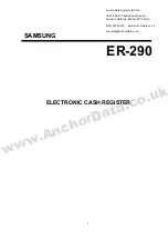
The following screen capture shows the PLC Setup setting from the CX-Pro-
grammer.
Word
Bits 8 to 15
Bits 0 to 7
R+2
W
5
R+3
1
1
R+4
1
5
R+5
2D (hexadecimal)
Input type (hexadecimal)
30: Normally open
31: Normally closed
15
R+2
R+3
R+4
W
5
1
1
1
5
Bit address written in ASCII
15
8
0
7
R+6
R+7
R+8
R+9
R+10
Summary of Contents for SYSMAC CS Series
Page 2: ......
Page 4: ...iv ...
Page 30: ...xxx ...
Page 186: ...146 List of Instructions by Function Code Section 2 4 ...
Page 1320: ...1280 Model Conversion Instructions Unit Ver 3 0 or Later Section 3 35 ...
Page 1390: ...1350 CJ series Instruction Execution Times and Number of Steps Section 4 2 ...
Page 1391: ...1351 Appendix A ASCII Code Table ASCII SP Four leftmost bits Four rightmost bits ...
Page 1392: ...1352 ASCII Code Table Appendix A ...
Page 1404: ...1364 Revision History ...