


1141
Failure Diagnosis Instructions
Section 3-30
Generating or Clearing User-defined Non-fatal Errors
The following table shows the function of the operands.
Note The value of operand N must be different from the content of A529
(the system-generated FAL/FALS number).
Note *Other settings would be constants #0200 through #FFFE or a word address.
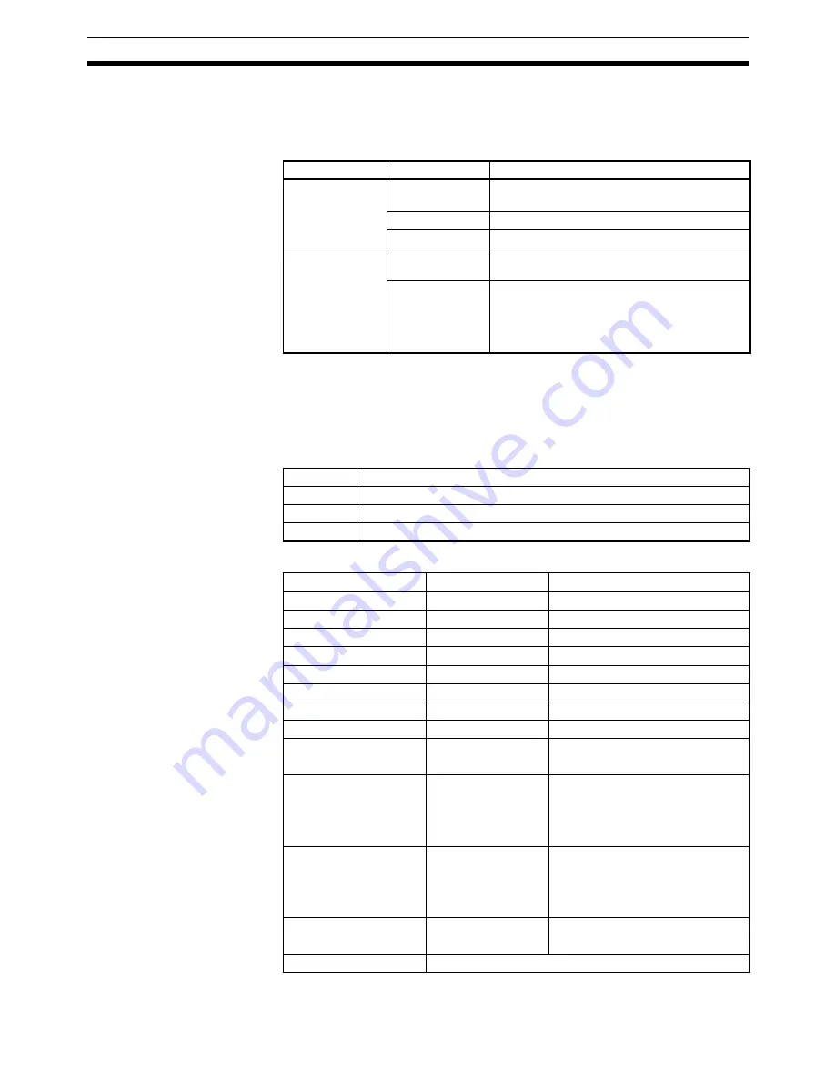
Generating Non-fatal System Errors (CS1-H, CJ1-H, CJ1M, or CS1D Only)
The following table shows the function of the operands.
Note The value of operand N must be the same as the content of A529
(the system-generated FAL/FALS number).
Operand Specifications
N
S
Function
0
#0001 to #01FF
Clears the non-fatal error with the correspond-
ing FAL number.
#FFFF
Clears all non-fatal errors.
Other*
Clears the most serious non-fatal error.
1 to 511
(These FAL num-
bers are shared
with FALS num-
bers.)
#0000 to #FFFF
Generates a non-fatal error with the corre-
sponding FAL number (no message).
Word address
Generates a non-fatal error with the corre-
sponding FAL number.
The 16-character ASCII message contained in
S through S+7 will be displayed on the Pro-
gramming Device.
Operand
Function
N
1 to 511 (These FAL numbers are shared with FALS numbers.)
S
Error code that will be generated. (See Description below.)
S+1
Error details code that will be generated. (See Description below.)
Area
N
S
CIO Area
---
CIO 0000 to CIO 6143
Work Area
---
W000 to W511
Holding Bit Area
---
H000 to H511
Auxiliary Bit Area
---
A000 to A959
Timer Area
---
T0000 to T4095
Counter Area
---
C0000 to C4095
DM Area
---
D00000 to D32767
EM Area without bank
---
E00000 to E32767
EM Area with bank
---
En_00000 to En_32767
(n = 0 to C)
Indirect DM/EM
addresses in binary
---
@ D00000 to @ D32767
@ E00000 to @ E32767
@ En_00000 to @ En_32767
(n = 0 to C)
Indirect DM/EM
addresses in BCD
---
*D00000 to *D32767
*E00000 to *E32767
*En_00000 to *En_32767
(n = 0 to C)
Constants
0 to 511
#0000 to #FFFF
(binary)
Data Registers
---
Summary of Contents for SYSMAC CS Series
Page 2: ......
Page 4: ...iv ...
Page 30: ...xxx ...
Page 186: ...146 List of Instructions by Function Code Section 2 4 ...
Page 1320: ...1280 Model Conversion Instructions Unit Ver 3 0 or Later Section 3 35 ...
Page 1390: ...1350 CJ series Instruction Execution Times and Number of Steps Section 4 2 ...
Page 1391: ...1351 Appendix A ASCII Code Table ASCII SP Four leftmost bits Four rightmost bits ...
Page 1392: ...1352 ASCII Code Table Appendix A ...
Page 1404: ...1364 Revision History ...