


793
Data Control Instructions
Section 3-18
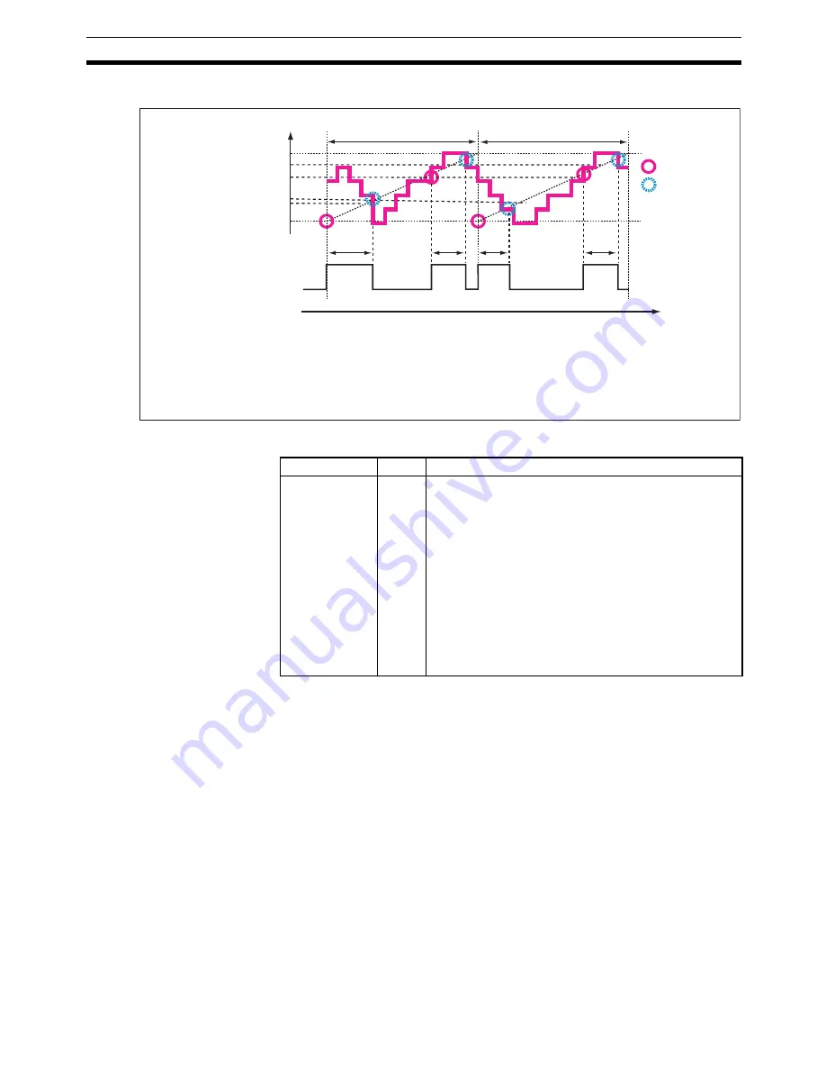
• Input time setting = 3 (Continuous adjustment)
Flags
Example
Example 1: Combining TPO(685) with PID(190)
When CIO 000000 is ON, TPO(685) takes the manipulated variable output
from PID(190) (contained in D00000), calculates the duty ratio from that
manipulated variable value (Duty ratio = MV
÷
MV range), converts the duty
ratio to a time-proportional output, and outputs the pulses to CIO 002001.
In this case, CIO 0020 is allocated to a Transistor Output Unit and bit
CIO 002001 is connected to a solid state relay for heater control.
100%
100%
a
×
0.35 s
0%
a
×
0.20 s
a
×
0.20 s
a
×
0.20 s
Control period (a)
Control period (a)
Output
Duty ratio
(MV/MV range)
: Output ON
: Output OFF
Time
Changes in the duty ratio are monitored in real time. If the duty ratio falls
below the initial value early enough, the duty ratio will be adjusted and the
output will be turned OFF sooner. If the duty ratio rises again after that,
the ratio will be adjusted again and the output will be turned ON. This
process is repeated continuously.
Use this setting to improve responsiveness when the control period is
relatively long and the duty ratio changes quickly. This setting is also
appropriate for lighting or power applications that require precise control.
Name
Label
Operation
Error Flag
ER
ON if the input data in S is out of range. (The input data
setting range depends on the input type setting.)
ON if the C data is out of range. (The manipulated vari-
able range will cause an error only when the input type is
set to manipulated variable.)
ON if the control period in C+1 is out of range.
ON if the output limit function is enabled but the output
lower limit (C+2) or output upper limit (C+3) is out of
range.
ON if the output limit function is enabled but the output
lower limit (C+2) is less than or equal to the output upper
limit (C+3).
OFF in all other cases.
Summary of Contents for SYSMAC CS Series
Page 2: ......
Page 4: ...iv ...
Page 30: ...xxx ...
Page 186: ...146 List of Instructions by Function Code Section 2 4 ...
Page 1320: ...1280 Model Conversion Instructions Unit Ver 3 0 or Later Section 3 35 ...
Page 1390: ...1350 CJ series Instruction Execution Times and Number of Steps Section 4 2 ...
Page 1391: ...1351 Appendix A ASCII Code Table ASCII SP Four leftmost bits Four rightmost bits ...
Page 1392: ...1352 ASCII Code Table Appendix A ...
Page 1404: ...1364 Revision History ...