348
Performance Characteristics
Appendix A
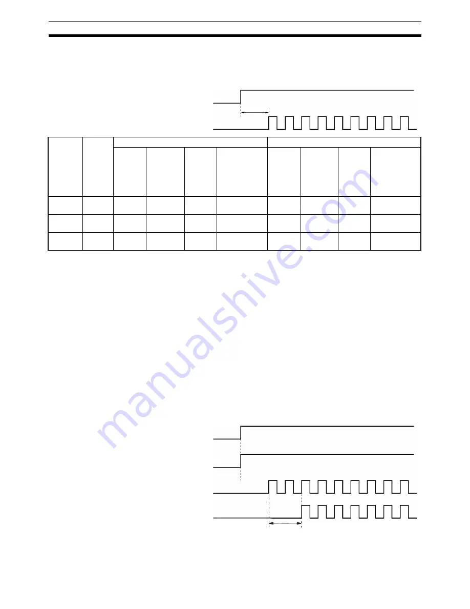
START Execution Time
The time required from when a START command is recognized until pulses are output will vary depending on
the combination of positions to be executed.
Note
The conditions under which the values in the above table hold are as follows:
• During the time between the START command being made at the PLC (END refresh) and the time at which
pulse output starts, no other commands are output (cycle time: 10 ms).
• The IOWR or IORD instructions are not executed.
• The IORF instruction is not executed.
• The Override Enable Bit is OFF.
• No data saving or data transfer operations are executed.
• Error counter reset output/origin-adjustment command output is OFF.
• CX-Position is not used.
• The following parameter settings are made:
Maximum speed: 200 kpps
Initial pulse designation: 1 (maximum speed set with axis’ parameters)
Acceleration/deceleration curve: Trapezoid
Even if the START commands for multiple axes are recognized simultaneously, there will be a discrepancy in
the actual pulse output.
START
Pulse output
Time
Opera-
tion
NC1
@
3
NC2
@
3
NC4
@
3
Y-axis
starting
while X
axis is
stopped
Y-axis
starting
while X
axis is
operating
X-axis
and Y-
axis
simulta-
neous
starting
Interpolation
starting from
X-axis (2-axis
control)
U-axis
starting
while X,
Y, and Z
axes are
stopped
U-axis
starting
while X,
Y, and Z
axes are
operating
X, Y, Z,
and U-
axis
simulta-
neous
starting
Interpolation
starting from
X-axis (4-axis
control)
Jogging
2 ms
max.
2 ms
max.
2.5 ms
max.
3 ms
max.
---
2 ms
max.
3 ms max. 4 ms
max.
---
Memory
operation
2 ms
max.
2 ms
max.
3 ms max. 3 ms
max.
3 ms max.
2 ms
max.
3.5 ms
max.
4 ms
max.
3.5 ms max.
Direct
operation
2 ms
max.
2 ms
max.
3 ms max. 3 ms
max.
---
2 ms
max.
3.5 ms
max.
4 ms
max.
---
START
Pulse output
Output
delayed
X
Y
X
Y
Summary of Contents for CJ1W-C113 - REV 02-2008
Page 2: ...CJ1W NC113 213 413 133 233 433 Position Control Units Operation Manual Revised February 2008 ...
Page 3: ...iv ...
Page 13: ...xiv ...
Page 15: ...xvi ...
Page 19: ...xx ...
Page 27: ...xxviii Conformance to EC Directives 6 ...
Page 43: ...16 Control System Principles Section 1 7 ...
Page 47: ...20 Basic Procedures Section 2 ...
Page 139: ...112 Examples of Parameter Settings Section 4 9 ...
Page 173: ...146 Transferring Data with CX Position Section 5 7 ...
Page 223: ...196 Sample Program Section 7 7 ...
Page 259: ...232 Sample Program Section 8 10 ...
Page 293: ...266 Easy Backup Function Ver 2 0 or later Section 9 11 ...
Page 369: ...342 Reading Error Information with CX Position Section 11 8 ...
Page 385: ...358 Common Parameter Area Appendix C ...


