


240
Interrupt Feeding
Section 9-3
9-3-3
Procedure for Direct Operation
When the Interrupt Feeding Bit is turned ON, positioning is started with speed
control and an interrupt input signal is awaited.
1,2,3...
1.
Set the operating data area using the parameters.
2.
Set the amount of interrupt feeding movement (position, speed, accelera-
tion/deceleration time number) in the operating data area. The sign of the
position at this point becomes the direction of travel after the input of the
interrupt signal. “+” means interrupt feeding in the direction of travel, while
“–” means interrupt feeding in the opposite direction.
3.
Set the direction of the speed control with the direction designation, and
then turn the Interrupt Feeding Bit from OFF to ON.
4.
When the external interrupt signal is input, interrupt feeding will be execut-
ed.
9-3-4
Beginning Words of Memory Areas
The beginning words of the operating memory area, operating data area, and
common parameter area used for a Position Control Unit (PCU) are deter-
mined (or set) according to the following.
• Beginning word of the operating memory area, n = CIO 2000 + 10
×
unit
number
• Beginning word of the common parameter area, m = 100
×
unit
number
• Beginning word of the operating data area, l, is specified in m and m+1.
Set the beginning words of the operating data area and designate the axis
parameters used with the common parameters as shown below.
9-3-5
Operating Memory Area Allocation and Operating Data Area
Settings
For details regarding positioning sequences in memory operation, see
8-4
Positioning Sequences
. Refer to
SECTION 8 Memory Operation
for how to
set and execute the operating data area and operating memory area when the
program has been started from memory operation.
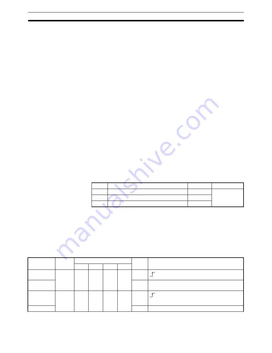
Operating Memory Area
Word
Name
Bit
Reference
m
Operating data area designation
00 to 15
SECTION 4
m+1
Beginning word of operating data area
00 to 15
m+2
Axis parameter designation
00 to 15
Name
Model
Operating memory area
Bit
Details
X axis Y axis Z axis U axis
Interrupt
feeding
NC4
@
3
NC2
@
3
NC1
@
3
n
n
n
n+2
n+2
n+4
n+6
05
Direction des-
ignation
10
1: CCW; 0: CW
Positioning
Completed
Flag
NC4
@
3
NC2
@
3
NC1
@
3
n+8
n+4
n+2
n+11
n+7
n+14
n+17
05
Busy Flag
13
1: Busy
: Start of interrupt feeding
: Positioning completed
Summary of Contents for CJ1W-C113 - REV 02-2008
Page 2: ...CJ1W NC113 213 413 133 233 433 Position Control Units Operation Manual Revised February 2008 ...
Page 3: ...iv ...
Page 13: ...xiv ...
Page 15: ...xvi ...
Page 19: ...xx ...
Page 27: ...xxviii Conformance to EC Directives 6 ...
Page 43: ...16 Control System Principles Section 1 7 ...
Page 47: ...20 Basic Procedures Section 2 ...
Page 139: ...112 Examples of Parameter Settings Section 4 9 ...
Page 173: ...146 Transferring Data with CX Position Section 5 7 ...
Page 223: ...196 Sample Program Section 7 7 ...
Page 259: ...232 Sample Program Section 8 10 ...
Page 293: ...266 Easy Backup Function Ver 2 0 or later Section 9 11 ...
Page 369: ...342 Reading Error Information with CX Position Section 11 8 ...
Page 385: ...358 Common Parameter Area Appendix C ...


