background image

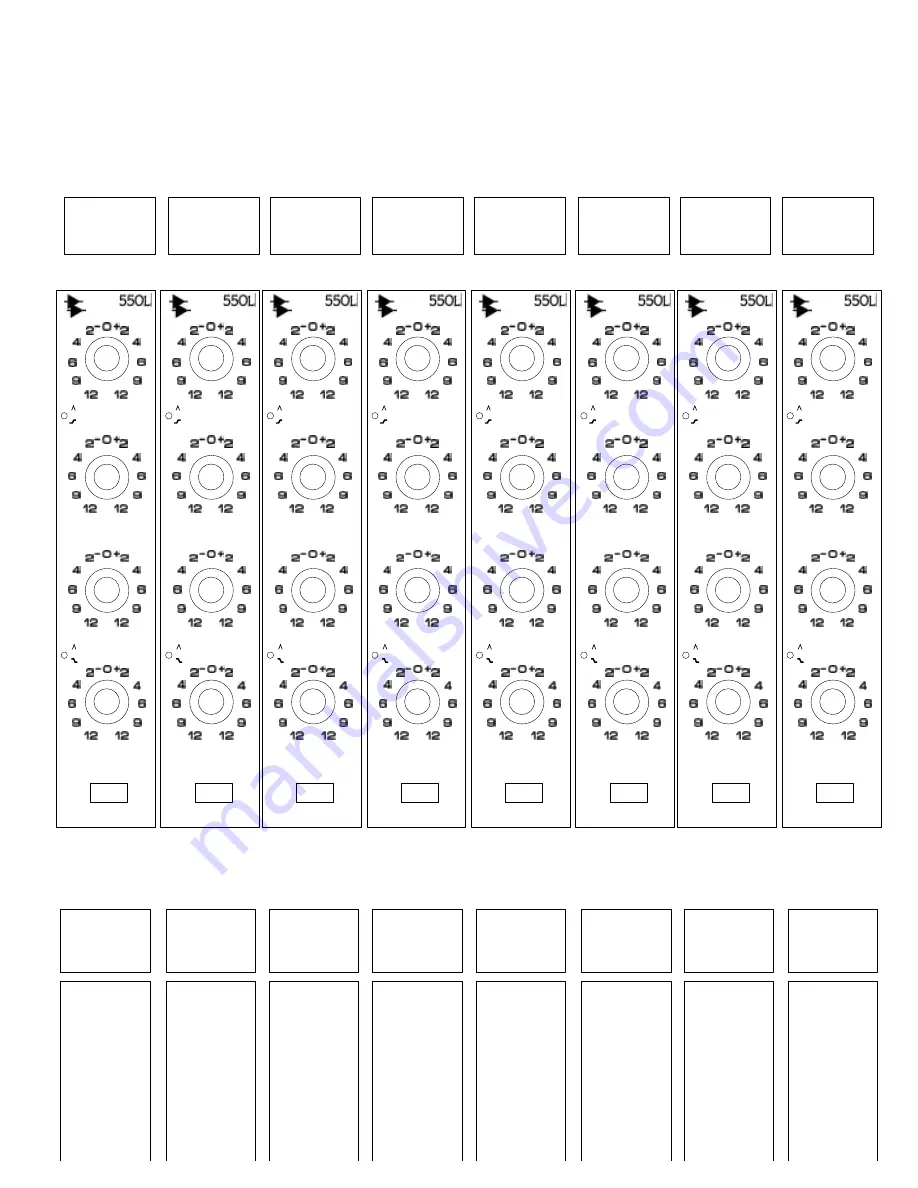
CHAN#

CHAN#

CHAN#

CHAN#

CHAN#

CHAN#

CHAN#

CHAN#

ARTIST:
ENGINEER:
DATE:

NOTES:
DRAWN BY:
STUDIO:

TITLE

NOTES

TITLE

NOTES

TITLE

NOTES

TITLE

NOTES

TITLE

NOTES

TITLE

NOTES

TITLE

NOTES

TITLE

NOTES

20k

15k

12.5k

10k

7k

5k

2.5k

400

200

100

50

40

30

1k

700

500

240

180

150

75

12.5k

10k

8k

5k

3k

1.5k

800

300

LF

HF

20k

15k

12.5k

10k

7k

5k

2.5k

400

200

100

50

40

30

1k

700

500

240

180

150

75

12.5k

10k

8k

5k

3k

1.5k

800

300

LF

HF

20k

15k

12.5k

10k

7k

5k

2.5k

400

200

100

50

40

30

1k

700

500

240

180

150

75

12.5k

10k

8k

5k

3k

1.5k

800

300

LF

HF

20k

15k

12.5k

10k

7k

5k

2.5k

400

200

100

50

40

30

1k

700

500

240

180

150

75

12.5k

10k

8k

5k

3k

1.5k

800

300

LF

HF

20k

15k

12.5k

10k

7k

5k

2.5k

400

200

100

50

40

30

1k

700

500

240

180

150

75

12.5k

10k

8k

5k

3k

1.5k

800

300

LF

HF

20k

15k

12.5k

10k

7k

5k

2.5k

400

200

100

50

40

30

1k

700

500

240

180

150

75

12.5k

10k

8k

5k

3k

1.5k

800

300

LF

HF

20k

15k

12.5k

10k

7k

5k

2.5k

400

200

100

50

40

30

1k

700

500

240

180

150

75

12.5k

10k

8k

5k

3k

1.5k

800

300

LF

HF

20k

15k

12.5k

10k

7k

5k

2.5k

400

200

100

50

40

30

1k

700

500

240

180

150

75

12.5k

10k

8k

5k

3k

1.5k

800

300

LF

HF

h. 550L 4-Band Equalizer

Summary of Contents for 7-22-10

Page 1: ...All Discrete Surround Mixing and Recording Console Operator s Manual REVISED 7 22 10 Written for Automated Processes Incorporated by Daniel Pfeifer 2010 ...

Page 2: ...500 Slot 550L EQ or 560L Graphic EQ 3 5 1068L Input Module 3 5 1 Equalizer Assignment 3 5 2 Auxiliary Sends 3 5 2 1 Master Auxiliary Mode Switches 3 5 2 2 Auxiliary Send Controls 3 5 2 3 AUX PRE MUTE 3 5 3 Tape Pad 3 5 4 Fader 2 Path Controls 3 5 5 Fader 1 Path Controls 3 6 Channel Faders 3 6 1 Fader 1 3 6 2 Fader 2 3 6 3 Position Faders 3 6 3 1 Setting Fader Positions 3 7 Channel Meters and Peak ...

Page 3: ...Masters 7 3 LFE Feed and Master 7 3 1 Creating a LFE Feed for 5 1 and 7 1 Surround Program Outputs 7 3 1 1 LFE Feed from a Mono Auxiliary Send 7 3 1 2 LFE Feed from Fader 1 and a Multitrack Summing Bus 7 3 1 3 LFE Feed from Fader 2 and a Multitrack Summing Bus 7 3 1 4 LFE Feed from an Unfiltered External Source 7 3 1 5 LFE Feed from a Filtered External Source 7 4 A B Feed and Master 7 4 1 Creating...

Page 4: ...Control Room Monitor Output and Amplifier Input Patch Points 13 6 5 1 Test Points 13 7 Studio Monitor Source Selection STUDIO and Level Control 13 7 1 Studio Monitor Controls 13 7 2 Studio Monitor Output and Amplifier Input Patch Points 14 0 User Controls 15 0 Oscillator Pink Noise Generator 15 1 Oscillator Pink Noise Generator Controls 15 2 Oscillator Pink Noise Generator Patch Points 16 0 Meters...

Page 5: ... 18 3 4 Fader Control Modules FCM 18 3 5 Fader Modules 18 3 6 1068L Input Modules 18 3 7 Output Assignment Modules Routing Panels 19 0 Vision Software 19 1 Starting Vision Software 19 2 Main Window 19 2 1 Title Bar 19 2 2 Menu Bar 19 2 2 1 File Menu 19 2 2 2 View Menu 19 2 2 3 Setup Menu 19 2 2 4 Tools Menu 19 3 Primary Windows 19 3 1 Channel Control 19 3 2 ACM Connection 19 3 3 Global Functions 1...

Page 6: ...uxiliary Send Routing 24 1 6 Global Settings and Routing 24 1 7 Clear Settings 24 1 8 Read Console 24 2 Recall System Procedures 24 2 1 Making Software Channel Output Assignments and Recallable Switch Settings 24 2 2 Saving Recall Settings in a Snapshot 24 2 3 Applying Saved Recall Settings from a Snapshot 24 2 4 Clearing Recall Settings on All Channels 25 0 Groups 25 1 Overview 25 2 Group Enables...

Page 7: ...s and Sections 26 4 1 Selecting Channel Sections Using Software 26 4 2 Global Channel Section Selectors 26 4 3 Channel Status Display 26 4 4 Selecting Channel Sections Using Hardware 26 5 Automation Modes and Submodes 26 5 1 Automation Modes 26 5 2 Mute Overwrite Mode 26 5 3 Automation Submodes 26 5 4 Assigning Automation Modes and Submodes 26 5 4 1 Channel Control Window Mode and Submode Assignme...

Page 8: ...control surface to control a DAW 28 0 System Setup Maintenance and Updates 28 1 Setup Menu 28 2 Software and Firmware Updates 28 2 1 Updating PC Software 28 2 1 1 Install or Update the Vision PC Software 28 2 2 Updating ACM Firmware 28 2 2 1 Program ACM Firmware 28 2 3 Updating FCM Firmware 28 2 3 1 Program FCM Firmware 28 2 4 Updating VCP Display Firmware 28 2 4 1 Program VCP Display Firmware 28 ...

Page 9: ...imiter h 550L Discrete 4 Band Equalizer i 560L Discrete 10 Band Graphic Equalizer v Console Module Setup Sheets a 205L Direct Input b 212L Microphone Preamp c 215L High pass Low pass Sweep Filter d 225L Channel Compressor e 235L Channel Noise Gate f 525 Re Issue Compressor g 527 Compressor Limiter h 550L 4 Band Equalizer i 560L 10 Band Graphic Equalizer j 1068L Input Module k Channel Fader l Group...

Page 10: ...Sends two stereo six mono all switchable between paths and pre post fader 40 600 Hz High Pass Sweep Filter in Fader 1 path 70 Hz High Pass Filter in Fader 2 path Assignable Equalizer as fitted o 550L 4 band o 560L 10 band Graphic Optional Processing as fitted o 205L Direct Input o 212L Microphone Preamplifier o 215L Sweep Filter o 225L Compressor o 235L Noise Gate o 525 Re Issue Compressor o 527 C...

Page 11: ...m the professional tools used to create audio masters From the mic amps and equalizers to the signal processing devices and right through the bus and routing structures of an audio console we applaud the rising levels of sonic expectation today s audio performances demand API proudly presents the Vision Recording and Mixing Console built to the same exacting standards of reliability sonic performa...

Page 12: ...console may be configured in many ways and each Vision console is built to meet the specifications determined by the owner While work flow capacity and patching may vary by configuration the basic operational premise of all Vision consoles is the same 1 2 1 Channel Bucket 16 Channel Bucket There are five module slots associated with each channel bucket in the Vision mainframe From the meter bridge...

Page 13: ...ion This is a custom option and may not be programmed on all consoles Refer to the studio engineering documents and staff for details on specific installations If the Upper 200 Slot used with for signal processing the upper slot is located before the lower slot in the signal flow NOTE See section 3 8 200 Slot Programming and Patching for details on 200 Slot routing 1 2 1 2 Lower 200 Slots The Lowe...

Page 14: ...o returns The Options Bucket can be fitted with the following modules 205L Direct Input 212L Microphone Preamplifier 215L Sweep Filter 225L Compressor Limiter 235L Noise Gate Expander 550L 4 Band EQ 560L 10 Band Graphic EQ 525 Re Issue Compressor 527 Compressor Limiter E1068L Stereo Surround Return Any combination of these modules may be installed When the Options Bucket is equipped with preamp mo...

Page 15: ... multitrack mixing session the channel signal paths function as follows Fader 1 accepts the returns from the multitrack recorder and other sources and routes them to any of the three Stereo Program Busses and or the Surround Program Bus Fader 2 can also carry multitrack returns and other sources to the Program Busses Fader 2 is fully automatable and has surround panning Fader 2 may alternately be ...

Page 16: ...he following signal processing modules o 215L Sweep Filter o 225L Compressor o 235L Gate Fader 1 and Fader 2 have the following features Insert Send and Return Phase Reverse Polarity Inverter Trim Peak Indicator High pass Filter o Fader 1 has a 40 600 Hz sweep filter o Fader 2 has a 70 Hz fixed filter Automatable Fader Mute Solo Activation 2 4 Channel Output Assignments Fader 1 and Fader 2 paths h...

Page 17: ...be routed pre or post the fader of the assigned path Aux Sends 1 6 are mono Aux Sends 7 8 and 9 10 are stereo Aux Sends 9 10 can be routed to feed the Multitrack Summing Busses 1 8 2 5 Channel Components Several sections of the console make up a complete Input Output I O Channel Channel Meter Upper 200 Slot Channel Input or Signal Processing o Microphone Preamp 212L OR o Direct Input 205L OR o 215...

Page 18: ...hey occur within the channel The various processes are shown as if they are engaged All block diagrams assume the following A 212L Preamp installed in the Upper 200 Slot Input Selector switches not engaged MIC TAPE FDR1 MIC or FDR2 TAPE FDR 1 switch not engaged on Fader 2 The Lower 200 Slot is Pre EQ in Fader 1 with a 225L Compressor installed Pan pots engaged These block diagrams do not show patc...

Page 19: ...4 Basic Multitrack Recording Block Diagram using Direct Out for the Multitrack Feed NOTE For mixing signal flow refer to the basic Fader 1 and Fader Block Diagrams If Fader 2 is used to feed the Program Busses the TAPE switch on the channel will need to be engaged ...

Page 20: ...uration is shown with a 550L EQ installed in the channel 500 slot and a 225L compressor installed in the upper 200 slot A USER button has been programmed to switch the upper 200 slot from post EQ in the Fader 1 audio path to post EQ in the Fader 2 audio path The meter positions indicated the feed to the channel VU meter when the adjacent button is engaged The output of each audio path is shown wit...

Page 21: ...ircuit ALL SAFE Prevents all of the current Input Selection for both paths from being changed Illuminates in yellow when engaged ALL CLEAR Resets the Input Selection to the default normal state Fader 1 TAPE Fader 2 MIC Illuminates in green when pressed FDR 2 TAPE Selects TAPE as the input source for FADER 2 on all channels Illuminates in green when engaged FDR 1 MIC Selects MIC as the input source...

Page 22: ...ws Output Level Transformer Coupled Output to 28 dBm All Discrete Design GAIN Sets the preamplifier gain 55 dB gain range VU Meter LED meter indicates output level 20 Inserts a 20dB Pad at the microphone input A red LED indictor illuminates when engaged 48V Provides 48 Volt Phantom Power to the Mic Preamp In patch point The Mic Tie Line Out patch points are fully normalled to the Mic Preamp In pat...

Page 23: ...er and Lower 200 Slots is dependent on which modules are installed and internal programming In a standard installation the Upper and Lower 200 Slots are grouped together for routing purposes The possible locations for the 200 Slots are Pre EQ Fader 1 Post EQ Fader 1 Pre EQ Fader 2 Post EQ Fader 2 NOTE A USER button in the Center Section can be programmed to change the location of the Upper 200 Slo...

Page 24: ...n access pin on the rear of the unit This modification requires a switch and custom wiring and is available at extra cost The controls for the 225L Compressor Limiter function as follows Features Threshold control from 20 to 10 dBu Variable compression ratio from 0 to infinity Fast Medium and Slow Attack Times Adjustable release time from 50ms to 3 seconds Old or New sound HARD or SOFT compression...

Page 25: ...ation so 0 to 9 dB is available for fine tuning of subtle undetectable gating The second half of rotation is from 10 to 80 dB for more drastic noise reduction The Expander function selects a 1 2 ratio allowing the signal to sneak up to the full signal level without any loss of under threshold nuances of vocals and percussion Setting the threshold in the Gate function to the desired level then swit...

Page 26: ... ON On Off switch Activates the module A green LED indicator illuminates when engaged DEPTH Sets the amount of attenuation gain reduction 0 to 80dB R H Release Hold Time Sets release or hold time 50ms to 3 seconds The Release or Hold function is determined by the HLD REL switch HLD REL Hold Release Switches the Release Time control to Hold Time HLD Hold The R H control determines Hold time Release...

Page 27: ...both continuously adjustable with a range from 20 Hz to 20 kHz in two bands The low pass filter has a range from 500 Hz to 20 kHz and the high pass filter has a range from 20 Hz to 600 Hz This covers a broad range of frequencies throughout the audio spectrum Because of the subtle nature of the 215L filter it finds a home with uses like rolling off the low end of a hi hat where a natural sound is d...

Page 28: ...s the center frequency for the selected band Center frequencies vary by band High 2 5kHz 5kHz 7kHz 10kHz 12 5kHz 15kHz 20kHz High Mids 800Hz 1 5kHz 3kHz 5kHz 8kHz 12 5kHz Low Mids 75Hz 150Hz 180Hz 240Hz 500Hz 700Hz 1kHz Lows 30Hz 40Hz 50Hz 100Hz 200Hz 300Hz 400Hz Frequencies are indicated in blue numbers Boost and Cut Ring Sets the amount of boost or cut for the selected band 12dB of boost or 12dB...

Page 29: ... o 4kHz o 8kHz o 16kHz 12 dB of boost or cut Hard bypass with indicator Each band has its own boost cut control The controls for the 560L EQ function as follows NOTE The switch on this module is not part of the Automation or Recall systems Boost and Cut Slider Sets the amount of boost or cut for the selected band 12dB of boost or 12dB of cut EQ On Off switch Activates the channel EQ Hard bypass wh...

Page 30: ...3 5 1068L Input Module ...

Page 31: ... added to the 7 8 and 9 10 Auxiliary Busses at the 227M Cue Master module Grand Master output Lt Rt Fold Down Matrix output Each of the Auxiliary Sends feed their respective Auxiliary Summing Bus The output of each of these Busses is fed to the corresponding 227L module in the Center Section There an External Input source may be selected and Talk Back may be added On Off Output Level Solo controls...

Page 32: ...TANT NOTE The source assignment Pre Post and Fader1 Fader2 is the same for both Stereo Auxiliary Sends 7 8 or 9 10 To make an Auxiliary Send source assignment do the following Press the desired Master Auxiliary Mode switch to activate one of the two Master Auxiliary modes indicated by its lit led Press the 1 3 5 and or 7 8 switch to make the desired source assignments Aux Sends are always assigned...

Page 33: ...8 switches serve as ON switches as well as second function switches for Auxiliary Send source assignments Pre or Fader2 The 2 4 6 9 10 switches serve solely as ON switches they play no role in source assignment The ON Switches may be controlled Locally from the 1068L module Via the automation system The 10 Auxiliary Sends on the 1068L module have Level or Level and Pan controls that are used to se...

Page 34: ...Pre fader from the assigned path Recall IMPORTANT NOTE Only one Stereo Auxiliary Send 7 and 8 or 9 and 10 may be used at a time In other words both Stereo Auxiliary Sends cannot be used simultaneously on the same channel IMPORTANT NOTE The source assignment Pre Post and Fader1 Fader2 is the same for both Stereo Auxiliary Sends 7 and 8 or 9 and 10 Stereo Aux Send 9 10 can be routed to feed the Mult...

Page 35: ...ing effects virtual tracks and other sources during mixdown LFE Send during mixdown Additional Aux Send during mixdown Creating stems and bouncing tracks Any other operation that needs a fully featured audio path Accordingly the Fader 2 audio path is equipped with the following features in the order they appear in the signal flow MIC or TAPE input selection Pre or Post EQ access to the channel 200...

Page 36: ...luminates when engaged FDR1 Fader 1 Output Routes the output of Fader 1 to the Fader 2 audio path The Fader 1 output is routed to the Fader 2 audio path POST the Insert Return and PRE the Phase Reverse It s useful for creating a LFE feed or an additional Aux Send using the Fader 2 audio path It s useful for creating stems and bouncing tracks Recall A green LED indicator illuminates when engaged Ø ...

Page 37: ...nction for Fader 2 The following solo functions may be selected via the Center Section o Pre fader Listen PFL Non destructive mono o After Fader Listen AFL Non destructive mono o Solo In Place SIP Destructive panned post fader Illuminates in yellow when engaged NOTE AFL is the default solo mode SAFE Activates the Solo Safe mode for Fader 2 The SAFE button protects Fader 2 from being muted when the...

Page 38: ...o the Lower 200 Slot if link is set Access to Channel Meter depending on Master Meter Selection Assignable EQ Insert Send and Return Phase Reverse Polarity Inverter Channel Trim Peak Indicator Full sized Automatable Fader High pass Sweep Filter Automatable mute Full Solo Functions Solo Safe Direct Output Stereo Surround Panning LCR Left Center Right Activates Left Center Right panning for Fader 2 ...

Page 39: ...inates when engaged Ø Phase Reverse Inserts a Phase Reverse Polarity Inverter in the Fader 1 audio path Recall A red LED indicator illuminates when engaged TRIM Sets the amount of pre fader level Trim boost 0 to 12dB of gain Located Pre fader so the added gain is reflected in all post fader stages Aux Sends Solos Bus Assignments and Direct Output PEAK A red LED illuminates when the preset Peak Ref...

Page 40: ...hannel is soloed Recall A yellow LED indicator illuminates when engaged LCR Left Center Right Activates Left Center Right panning for Fader 2 Activates the feed to the Center Program Bus from the pan pot Audio panned Front and Center is fed to the Center Program Bus Audio panned Front and Center is not fed to the Left and Right Program Busses Stereo Left Right panning is selected by default Recall...

Page 41: ...d automatable Fader 1 and or Fader 2 faders can be set to a common position on a global basis via software Each fader is located before the High pass Filter and Mute switch at the end of each audio path Details pertaining to each individual fader are included in the following sections 3 6 1 Fader 1 The Fader 1 fader is located in the Fader Module at the bottom of a complete channel strip It is the...

Page 42: ...of the Fader 2 faders and vice versa Faders can be set to the following positions 10 dB 5 dB 0 dB 5 dB 10 dB 15 dB 20 dB 25 dB 30 dB 40 dB 50 dB 60 dB 70 dB 80 dB 92 dB For example Position Faders can be used to quickly set all of the Fader 2 faders to 0 dB unity gain at the start of a tracking date FADER 2 Controls the output level of the Fader 2 audio path When the Fader is set to 0dB the audio ...

Page 43: ... checkbox Click to apply the selected fader position to the selected faders and close the window Click to apply the selected fader position to the selected faders and leave the window open Click to cancel the operation without positioning the faders and close the window Important Note Positioning faders will move the selected faders from their current positions Any current mix positions will be lo...

Page 44: ... feed to the Channel Meter is determined by the selection made using the METER SELECT controls in the Center Section VU FDR 1 Fader 1 Assigns the meters to the Fader 1 Channel Input Illuminates in green when engaged VU FDR 2 Fader 2 Assigns the meters to the Fader 2 Channel Input Illuminates in green when engaged VU DIR Direct Output Assigns the meters to the Channel Direct Output Illuminates in g...

Page 45: ...hen a patch cord is inserted In other words the signal continues to its Normalled destination as well as through the inserted patch cord in essence creating a Y cord NOTE The MIC TIE LINE OUT Patch Points are the only Patch Points that break when a patch cord is inserted Inputs All input Patch Points break when a patch cord is inserted In other words the signal is diverted through the inserted pat...

Page 46: ...nto the COMP SIDE CHAIN IN will replace the Compressor Input as the input to the module s detection path side chain GATE IN Gate Input 200 Slot Input Half normalled to KEY INPUT KEY IN Gate Key Input 200 Slot Key Input Half normalled from GATE IN GATE OUT Gate Output 200 Slot Output Returns Pre or Post EQ in the programmed audio path Fader 1 or Fader 2 See 200 Slot Patching below NOTE Patching int...

Page 47: ... FADER 2 INSERT SEND Fader 2 Insert Send Always active FADER 2 INSERT RETURN Fader 2 Insert Return Replaces the feed to the channel Fader Input when the Fader 2 INS switch is engaged The Fader 2 Insert is Located Post EQ or the 200 Slot Output if so programmed Pre FADER 2 FDR INPUT FADER 1 CHANNEL INPUT Fader 1 audio path input Replaces the feed to the Fader 1 Channel Input The FADER 1 CHANNEL INP...

Page 48: ...Send Audio Path The patch points below are the patch points normally associated with the Fader 2 audio path during a typical multitrack recording session In this scenario Fader 2 is used to route microphone inputs to a multitrack recorder via the Direct Output EQUALIZER INPUT Equalizer Input 500 Slot In Replaces the feed to the Equalizer Input Post the CHANNEL INPUT EQUALIZER OUTPUT Equalizer Outp...

Page 49: ...t Return Pre Phase Reverse Polarity Inverter FADER 2 INSERT SEND Fader 2 Insert Send Always active FADER 2 INSERT RETURN Fader 2 Insert Return Replaces the feed to the channel Fader Input when the Fader 2 INS switch is engaged The Fader 2 Insert is Located Post EQ or the 200 Slot Output if so programmed Pre FADER 2 FDR INPUT EQUALIZER INPUT Equalizer Input 500 Slot In Replaces the feed to the Equa...

Page 50: ...MP SIDE CHAIN IN Compressor Side Chain Input 200 Slot Side chain Input Half normalled from COMP IN COMP OUT Compressor Output 200 Slot Output Returns Pre or Post EQ in the programmed audio path Fader 1 or Fader 2 See Lower 200 Slot Patching below DIRECT OUTPUT Channel Direct Output Fed from FADER 1 by default Will be fed from Fader 2 if the DIR switch is engaged The Direct Output is located Post t...

Page 51: ...taff for the 200 Slot programming of each installation Using the 225L Compressor as an example the routing to and from a 200 Slot is stated below for each of the possible slot locations Fader 1 Pre EQ Mic Tape switch output to COMP IN COMP OUT to pre FADER 1 CHANNEL INPUT Fader 1 Post EQ EQ Bypass switch output to COMP IN COMP OUT to Fader 1 path pre INSERT SEND Fader 2 Pre EQ Mic Tape switch outp...

Page 52: ... audio path Fader 1 or Fader 2 NOTE Patching into the COMP SIDE CHAIN IN will replace the Compressor Input as the input to the module s detection path side chain GATE IN Gate Input 200 Slot Input Half normalled to KEY INPUT KEY IN Gate Key Input 200 Slot Key Input Half normalled from GATE IN GATE OUT Gate Output 200 Slot Output Returns Pre or Post EQ in the programmed audio path Fader 1 or Fader 2...

Page 53: ...Right surround panning Tape Tape Input Follow Fader 1 Input from Fader 1 Direct Direct Output Global Tape Pad EQ to Fader 2 3 10 2 Recallable Auxiliary Send Routing The following Auxiliary Send and Global routing options may be set stored and recalled using the recall system Stereo Sends Auxiliary Send Routing Send 1 2 PRE Send 1 2 FDR 2 Send 3 4 PRE Send 3 4 FDR 2 Send 5 6 PRE Send 5 6 FDR 2 Send...

Page 54: ... Auxiliary Send 2 On Off Auxiliary Send 3 On Off Auxiliary Send 4 On Off Auxiliary Send 5 On Off Auxiliary Send 6 On Off Auxiliary Send 7 8 On Off Auxiliary Send 9 10 On Off NOTE The Fader 1 and Fader 2 channel faders are also automatable ...

Page 55: ... all Program Busses may be made from both paths simultaneously This allows both the Fader 1 and Fader 2 audio paths to contribute to the Program Busses during mix down This means a Vision console with 48 channels provides 96 automated channels with surround panning while mixing Assignments to the Multitrack Summing and Program Busses may be made in two ways Hardware Using the 16 channel Output Ass...

Page 56: ...umming Busses 1 24 Stereo Program Bus A Stereo Program Bus B Stereo Program Bus C Surround Program Bus 4 2 1 Channel Output Display There is a Channel Output Display for every channel It displays the current output routing assignments for the Fader 1 and Fader 2 audio paths Multitrack Summing Bus assignments 1 24 Stereo Program Bus assignments ST A ST B ST B Surround Program Bus assignments 5 1 Pa...

Page 57: ...uttons in the multitrack routing section of the Output Assignment module function as follows SET Assigns the associated channel to the selections made using the Bus Assignment buttons see below 1 25 thru 24 48 Multitrack Summing Bus Readies the selected Multitrack Summing Busses for assignment Assignments are not made until a channel SET button is pressed A green or yellow LED indicator illuminate...

Page 58: ... Program Bus The Fader 1 and Fader 2 audio paths each have a Program Bus Assignment section Assignments may be made to the following Program Busses ST A Stereo A ST B Stereo B ST C Stereo C 5 1 Surround The Pan pot in each path may also be engaged ST A Stereo A Readies Stereo Program Bus A for assignment Assignments are not made until a channel SET button is pressed A green LED indicator illuminat...

Page 59: ... the assignment buttons for the desired Program Busses to select them for assignment 4 Press the SET button on the channels to be assigned 4 2 8 Auxiliary Send 9 10 Assignment Procedure To make Program Bus assignments perform the following procedure 1 Press the CLEAR button to clear any previous assignment selections 2 Press the 9 10 assignment button to select stereo Aux Send 9 10 to feed the Mul...

Page 60: ...plied to the console at a later time Note Only channel output assignments will be covered in this section of this manual Complete details for using the recall system for channel setup and snapshots refer to section 24 0 Recall System 4 3 1 Recall Settings Window The Recall Settings window is the primary interface with the recall system The Recall Settings window provides control over the following...

Page 61: ...unless Shift Click or CTRL Click methods are used Channels or Channel can be added or deleted to previously selections using Shift Click or CTRL Click methods Rubber banding can be used in combination with Shift Click and Ctrl Click methods 4 3 3 Channel Status Indication Assignments made on the console control surface are not automatically reflected in the Recall Settings window To see any hardwa...

Page 62: ...signs Fader 2 to the Stereo B Program Bus Stereo A Assigns Fader 2 to the Stereo A Program Bus 5 1 Assigns Fader 2 to the Surround Program Bus An empty checkbox indicates the output is not assigned on any of the channels selected in the Channel Grid Clicking in any empty checkbox will assign the selected channel s to that output A checkmark will appear in the box indicating the assignment has been...

Page 63: ...Summing Busses Only one audio path Fader 1 or Fader 2 can feed the Multitrack Summing Busses at one time Pan to 24 Bus Enables Odd Even panning to the Multitrack Summing Busses Direct Controls the DIR Direct Switch Clear All Clears unchecks all output assignments and recallable switch settings for the selected channels Clear Busses Clears all Multitrack Summing assignments for the selected channel...

Page 64: ...ecall settings perform the following procedure 1 Make sure the console hardware is set as desired for the new snapshot 2 Open the Recall Settings window using the View menu in the Main window 3 Click the Read Console button in the Recalls Setting window to make sure the console settings match the settings in the recall system memory buffer 4 With a Project open click the Snapshot tab 5 Right click...

Page 65: ...t List and select Apply Snapshot from the menu The Apply Snapshot window will open 5 Select one or more channels using the Channels To Apply selection grid or click the All Available button to select all the available channels 6 Select the channel sections to include in the snapshot using the checkboxes in the Sections to Save section Make sure the Recall Switches checkbox is checked 7 Select an A...

Page 66: ...ay alternately be fed from the channel Direct Outputs by patching the DIRECT OUT patch points to the desired multitrack recorder input interface 5 2 Multitrack Output Trim Module Each Multitrack Summing Bus has an Output Trim just before the BUS OUTPUT patch points The Multitrack Output Trims are located in the Center Section Controls for the Multitrack Output Trims are as follows The output of th...

Page 67: ...Will be fed from Fader 2 if the DIR switch is engaged The Direct Output is located Post the Direct Output switch Post fader Note The DIRECT OUTPUT patch points are associated with the channels and are not part of the Multitrack Summing Bus system Since Direct Outputs are commonly patched to feed the multitrack recorder their patch points are shown here MULTITAPE OUTPUT Multitrack Recorder Output M...

Page 68: ... A ST B Stereo Bus B ST C Stereo Bus C The output of the Master Faders for these three stereo Busses may be mixed to a Grand Master Bus Grand Master Fader and output Each of the Stereo Program Bus assignments feeds its respective Stereo Program Bus A B and or C These Busses are fed to the associated Active Combining Amplifiers ACA The patch points from the three Stereo Bus ACA outputs STEREO ACA O...

Page 69: ...Grand Master A stereo Grand Master Bus and Grand Master Fader are provided to facilitate a wide range of operations The three Stereo Program mixes an External Input and the output of the Lt Rt Fold Down Matrix may be selected for mixing to the stereo Grand Master Bus Left and Right calibration trim pots CAL L R are provided for the primary Grand Master sources to assure precision summing The Stere...

Page 70: ...to the 2Track Feed 2T FEED distribution patch points There are five 5 sources that may be selected as sources to feed the Grand Master Bus ST A Stereo A Output of the Stereo A boosters ST B Stereo B Output of the Stereo B boosters ST C Stereo C Output of the Stereo C boosters EXT External Output of the GM EXT IN patch points Lt Rt Fold Down Matrix Output of the Lt Rt Fold Down Matrix o TO GM butto...

Page 71: ... to four 4 2 track recorders 2T1 IN 2T2 IN 2T3 IN and 2T4 IN patch points 6 4 Stereo Program Signal Flow The diagram below shows the basic Stereo Program Bus signal flow from the channel Stereo Bus Assignment through the Stereo Masters and Grand Master to the 2Track Feed ...

Page 72: ... external Grand Master inputs Allows an external stereo source to be added to the Grand Master mix Feeds the Grand Master ACA Active only when the EXT switch in the Grand Master Select controls is engaged GM ACA OUT Stereo Grand Master ACA output Half normalled to GM FDR IN GM FDR IN Feeds the Grand Master Fader Half normalled from GM ACA OUT Patching to these points will replace the feed to the G...

Page 73: ...els before the ACA Boosters calibrate the outputs of the Master Faders The outputs of the boosters SURROUND BSTR OUT are half normalled to the Surround Feed Inputs SURROUND FEED IN distribution patch points The SURROUND FEED IN distribution patch points are half normalled to feed to up to four 4 surround recorders 8TRACK1 IN 8TRACK 2 IN 8TRACK 3 IN and 8TRACK 4 IN The SURROUND FEED IN distribution...

Page 74: ...less one is created through routing and patching There is no LFE Program Bus or ACA There is no access to the LFE program outputs from the channel or E1068L pan pots NOTE While one of the SURROUND ACA OUT patch points is labeled LFE there is no LFE ACA 7 3 1 Creating a LFE Feed for 5 1 and 7 1 Surround Program Outputs The LFE Filter is part of the Monitor Control system and is not part of the Surr...

Page 75: ...e the LFE FLTR LFE Filter button in the Center Section to activate the LFE Filter 5 Select the LFE frequency 80 Hz default or 120 Hz 6 Patch the output of the FLT OUT Filter Out patch point to the LFE Master Fader input LFE SURROUND FADER IN patch point The diagram below shows the routing for a LFE feed from mono Auxiliary Send 1 In this scenario mono Auxiliary Send 1 feeds the LFE Filter The outp...

Page 76: ...Select the LFE frequency 80 Hz default or 120 Hz 7 Patch the output of the FLT OUT Filter Out patch point to the LFE Master Fader input LFE SURROUND FADER IN patch point The diagram below shows the routing for a LFE feed from Fader 1 and Multitrack Summing Bus 1 In this scenario Fader 1 is assigned to feed Multitrack Summing Bus 1 which feeds the LFE Filter The output of the LFE Filter feeds the L...

Page 77: ...LT OUT Filter Out patch point to the LFE Master Fader input LFE SURROUND FADER IN patch point The diagram below shows the routing for a LFE feed from Fader 2 and Multitrack Summing Bus 1 In this scenario Fader 2 is assigned to feed Multitrack Summing Bus 1 which feeds the LFE Filter The output of the LFE Filter feeds the LFE Surround Master Fader associated booster and output to the SURROUND FEED ...

Page 78: ...edure 1 Patch the output of the source to the LFE Master Fader input LFE SURROUND FADER IN patch point 2 Engage the LFE BYP LFE Bypass button in the Center Section to remove the LFE from the Control Room monitor system In this scenario the LFE Surround Master Fader is fed from the filtered external source The output of the LFE Master Fader is fed to its associated booster and output to the SURROUN...

Page 79: ...re turned on and turned up The diagram below shows the routing for A B feed from stereo Auxiliary Send 9 10 and a LFE feed from mono Auxiliary Send 1 In this scenario mono Auxiliary Send 1 feeds the LFE Filter The output of the LFE Filter feeds the LFE Surround Master Fader Stereo Auxiliary Send 9 10 feeds the A B Surround Master Fader The Master Faders feed the associated boosters and outputs to ...

Page 80: ... Bus 1 In this scenario Fader 1 is assigned to feed Multitrack Summing Bus 1 which feeds the LFE Filter The output of the LFE Filter feeds the LFE Surround Master Fader Fader 1 is also assigned to feed Multitrack Summing Busses 5 and 6 which feeds the A B Surround Master Fader The Pan pot is also engaged on these channels to facilitate panning between the 5 and 6 busses A and B channels The Master...

Page 81: ...which feeds the LFE Filter The output of the LFE Filter feeds the LFE Surround Master Fader Fader 2 is also assigned to feed Multitrack Summing Busses 5 and 6 which feeds the A B Surround Master Fader The Pan pot is also engaged on these channels to facilitate panning between the 5 and 6 busses A and B channels The Master Faders feed the associated boosters and outputs to the SURROUND FEED to the ...

Page 82: ...ght Center LFE Left Surround Right Surround Busses The last fader is a 5 1 Control Group Master 5 1 An A B Master Fader is not included in this configuration The 7 1 configuration is the same as 5 1 except a console configured for 7 1 mixing will have an audio master fader for the A B Surround Program A 5 1 Control Group Master Fader is not included in this configuration NOTE One of the six 6 Cont...

Page 83: ...ision console This matrix allows a stereo mix to be automatically created from the Surround Program while the surround mix is being made The controls for the Lt Rt Fold Down Matrix function as follows Balance Left Right balance control for the Front Left and Right matrix feeds L R Left Right Level control for the Front Left and Right channel contributions to the Lt Rt Fold Down Center Level contro...

Page 84: ...the Lt Rt OUT patch points when not CUT OUTPUT TO GM Output To Grand Master Routes the output from the Lt Rt Fold Down Matrix to the Grand Master Bus Fed from the Lt Rt MASTER LEVEL output Illuminates in white when engaged OUTPUT MUTE mutes the output from the Lt Rt Fold Down Matrix Fed from the Lt Rt MASTER LEVEL output Illuminates in white when engaged CR PLAY Control Room Playback Routes the cu...

Page 85: ... 0 Surround Signal Flow without LFE The diagram below shows the basic five channel Surround Program signal flow from the channel Surround Bus Assignment to the 8Track Feed and Lt Rt Fold Down No LFE or A B program outputs are included ...

Page 86: ... below shows a 5 1 Surround Program signal flow including a LFE Program output A LFE feed may be created by patching the output of a mono Auxiliary Send or a Multitrack Summing Bus to the LFE SURROUND FADER IN patch point No A B Program outputs included ...

Page 87: ... diagram below shows a 7 1 Surround Program signal flow including LFE and A B Program output The LFE and A B feeds may be created by patching the output of Auxiliary Sends or a Multitrack Summing Busses to the LFE and A B SURROUND FADER IN patch points ...

Page 88: ...d A B SURROUND ACA OUT patch points are not connected and carry no audio SURROUND FADER IN Surround Master Fader inputs Feeds the Surround Master Fader inputs An LFE Program feed can be created by patching LFE audio to the LFE SURROUND FADER IN Half normalled from SURROUND ACA OUT Patching to these points will replace the feed to the Surround Master Faders with the patch cord signal SURROUND BSTR ...

Page 89: ...e source routing Only one Stereo Auxiliary Send 7 8 or 9 10 may be used at one time In other words both Stereo Auxiliary Sends cannot be used simultaneously on the same channel Talk Back may be added to any Auxiliary Send as needed Aux Sends 9 10 may be routed to Multitrack Summing Busses 1 8 to provide addition summing outputs NOTE When Aux Sends 9 10 are routed to the Multitrack Summing Busses t...

Page 90: ...put level control Feeds the 227L SEND OUT patch points A green LED indicator illuminates when engaged EXT IN External Input Activates the 227L External Input Adds the signal from the External Input patch points 227L Send EXT IN to the Aux Send audio when engaged A red LED indicator illuminates when engaged T B IN Talk Back Input Routes Talk Back to the Aux Send Adds the Talk Back output from the 2...

Page 91: ...g sources may be added to the 7 8 and 9 10 Aux Busses Grand Master output Lt Rt Fold Down Matrix output This is used primarily to send the selected Program mix es to the headphones while recording Sends from individual channels may be added to the Program mix es This can be very handy for creating quick cue mixes with ability to reinforce certain tracks as needed LEVEL Stereo Master level control ...

Page 92: ...preamp is routed to the Talk Back controls in the Center Section for further distribution REV T B Reverse Talk Back Level control for the Reverse Talk Back microphone preamplifier An input for an external Talk Back microphone for Studio Talk Back is provided The output of the Reverse Talk Back microphone preamp is routed to the Talk Back controls in the Center Section for further distribution 227L...

Page 93: ...E1068L Stereo Surround Return module is a fully featured echo return with surround panning capabilities It offers a powerful suite of controls that provides the flexibility to handle a wide range of applications As many as twenty one 21 E1068L Echo Return modules can be installed in the Options Bucket NOTE The E1068L Stereo Surround Return is two 2 units wide Each one occupies two 2 200 Slots in t...

Page 94: ...nning Stereo Left Right panning is selected by default Feeds front center panned audio to the Center Program Bus and removes the signal from the Left and Right Busses when engaged A yellow LED indicator illuminates when engaged SOLO Activates the AFL After Fader Listen solo function Feeds the stereo Solo Bus when engaged Non destructive A yellow LED indicator illuminates when engaged SAFE Activate...

Page 95: ...he diagram below shows an example of routing of E1068L Echo Returns outputs for stereo mixing applications Two 1068L modules are shown in this example but as many as twenty one 21 1068L modules can feed the FX Return Active Combing Amplifiers ACA ...

Page 96: ...L modules are shown in this example but as many as twenty one 21 1068L modules can feed the FX Return Active Combing Amplifiers ACA 9 1 3 E1068L Patch Points E1068L SURROUND RETURN 1 9 Inputs to the E1068L modules FX RETURN SUR ACA OUT Effects Return Surround ACA Output Outputs from the Surround Effects Return ACAs All E1068L modules feed the Effects Return ACAs ...

Page 97: ...on for the specifics of each console The operation of these modules is covered earlier in the manual 9 3 Options Bucket Patch Points Patch points for 200 Slot modules in the Options Bucket may appear in the patch bay in various configurations OPTIONS LINE IN Options Bucket 200 Slot Input Half normalled to OPTIONS SIDE CHAIN IN OPTIONS SIDE CHAIN IN Options Bucket 200 Slot Side chain Input Half nor...

Page 98: ...ters do not pass audio but are designed to control other faders and mutes on the console In addition to the Control Group Master faders any other fader input channels Fader A B or any Program master fader can be assigned as group masters Group masters may be assigned to other group masters to create grand masters not the same as the Stereo Program Bus Grand Master Assignments are made via Vision s...

Page 99: ... Section The channel SOLO buttons may be engaged in one of the following solo activation modes Momentary MOM The solo function will be active only while a SOLO button is held down o One or more SOLO buttons may be engaged at once o The solo function will be deactivated when all SOLO buttons have been released Additive ADD Multiple SOLO buttons may be engaged at once o Any pressed SOLO buttons will...

Page 100: ...ader Listen solo mode of for all solos Illuminates in yellow when engaged SOLO CLR Solo Clear Disengages any engaged SOLO buttons Momentary does not stay engaged Illuminates in yellow when pressed AUX PRE MUTE Links the channel MUTE button with the Pre Fader Aux Sends All Pre fader Aux Sends mute when a channel MUTE button is engaged Illuminates in yellow when engaged MOM Momentary Activates the M...

Page 101: ...ormal engaged are not recorded to automation LATCH Latch Activates the Latch solo activation mode Only one SOLO button may be engaged at once A SOLO button will remain engaged when pressed and released The engaged SOLO button will be disengaged by pressing a it second time Pressing a second SOLO button while one is already engaged will disengage the active SOLO button and engage the second one The...

Page 102: ...Access Patch Points Solo Groups Replaces the function of the MUTE buttons with an additive solo in place function within a current group To activate the Solo Groups mode o Select Solo Groups from the Solo submenu in the ACM o Click the Solo Groups button in the Global Functions window in the PC software When Solo Normal is engaged o SG will appear VCP main display o The Solo Groups button in the G...

Page 103: ... following destinations All 227L Cue Send modules with the T B switch engaged Studio Loudspeakers Program and Multitrack Summing Busses An individual level control is provided for each destination Talk Back to each of these destinations can be activated individually or as part of the COM PRESET group Each destination may be assigned to the COM PRESET group individually 12 2 Reverse Talk Back A ded...

Page 104: ...to the COM PRESET group BUS Adds the Program and Multitrack Summing Busses to the COM PRESET group CUE Adds the Cue Sends to the COM PRESET group REV Reverse Talk Back Activates Reverse Talk Back STU Studio Activates Talk Back to the Studio Loudspeakers BUS Studio Activates Talk Back to the Program and Multitrack Summing Busses CUE Activates Talk Back to the Cue Sends All TALK buttons are momentar...

Page 105: ...t to a 2nd set of speakers Monitor output calibration and test points 13 1 Stereo Monitoring Support is provided for three 3 complete 7 1 surround control room monitoring systems The Left and Right speakers for the active system are used for stereo monitoring The source for the stereo monitors may be selected from nine 9 total sources five 5 internal or four 4 external The following sources may be...

Page 106: ...ear Source selection Lock Surround Main and Alternate Studio Monitor feeds Control Room Monitor Insert 13 2 1 Bass Management The Vision console provides a comprehensive suite of Control Room monitor bass management functions and LFE routing options These functions include LFE Filter activation LFE Filter bypass Switchable LFE Filter frequencies 80 and 120 Hz 5 Channel surround to LFE Filter fold ...

Page 107: ...urround LCR monitors while defeating the subwoofer feed This allows monitoring of the full surround content without the use of a subwoofer 13 2 2 LFE And Control Room Insert Controls The controls for the LFE Filter and bass management are located in the Center Section The Control Room Insert activation switch is included with these controls The LFE and Control Room Insert controls function as foll...

Page 108: ...uted to the Left Center and Right monitor feeds when the LFE TO LCR button is engaged LFE FILTER IN Input to the LFE low pass filter Three parallel non breaking inputs The signals patched to these points are summed together and fed to the LFE SURROUND MNTR INSERT SEND Surround Monitor Insert Send 8 channel Control Room Monitor Insert Send L R SL SR C LFE and A B channels are supported Always activ...

Page 109: ... Output of the Stereo B Program Master ST C Output of the Stereo C Program Master NOTE The 5 1 MIX Program Monitor selector supports 5 1 and 7 1 mixes The following Playback returns may be selected as the Control Room monitor source 6T1 6 Track 1 Return from 8 Track recorder playback device 1 6T2 6 Track 2 Return from 8 Track recorder playback device 2 6T3 6 Track 3 Return from 8 Track recorder pl...

Page 110: ...T B Stereo B Selects the output of Stereo Program Master B as the Program Monitor source ST A Stereo A Selects the output of Stereo Program Master A as the Program Monitor source ST GM Stereo Grand Master Selects the output of Stereo Grand Master as the Program Monitor source FOLD DOWN Selects the output of Lt Rt Fold Down Matrix as the Program Monitor source 5 1 MIX Selects the output of 5 1 or 7...

Page 111: ...ource 6T4 6 Track 4 Selects the return from 8 Track Record Playback device 4 as the Playback Monitor source 6T3 6 Track 3 Selects the return from 8 Track Record Playback device 3 as the Playback Monitor source 6T2 6 Track 2 Selects the return from 8 Track Record Playback device 2 as the Playback Monitor source 6T1 6 Track 1 Selects the return from 8 Track Record Playback device 1 as the Playback M...

Page 112: ...sters Post Master Fader Half normalled to STEREO GM SELECT IN Stereo Grand Master Selector inputs GM BSTR OUT Grand Master Booster Outputs Feeds the ST GM Stereo Grand Master Program Monitor Selector Outputs from the Stereo Grand Master Fader Boosters Post Grand Master Fader Half normalled to 2T FEED IN Lt Rt OUT Left Total Right Total Outputs Feeds the FOLD DOWN Lt Rt Fold Down Matrix Program Mon...

Page 113: ...IN 8 TRACK CONTROL ROOM MNTR IN 8 Track Control Room Monitor Inputs Feeds the Control Room monitor surround Playback source selectors Feeds the 6T1 6T2 6T3 and 6T4 Playback Monitor Source Selectors Half normalled from 8 TRACK 1 4 OUT Patching to these points will replace the feed to the 6 Track Monitor Selectors with the patch cord signal SURROUND MNTR INSERT SEND Surround Monitor Insert Send 8 ch...

Page 114: ...Selection CONTROL ROOM The Vision console provides support for three 3 complete 7 1 surround Control Room monitoring systems The Left and Right speakers for the active system are used for stereo monitoring The Front and Rear speaker feeds may be summed to mono independently The Front and Rear speakers may be reversed Flipped Front to Rear Rear to Front The CONTROL ROOM section of the center sectio...

Page 115: ...rnate 2 Control Room monitor system Illuminates in green when engaged ALL CUT Cuts the feed to all Control Room speaker feeds Illuminates in red when engaged DIM Activates the Control Room monitor Dim function Attenuates the output to the active Control Room monitor system by the amount set with the DIM LEVEL Illuminates in yellow when engaged DIM LEVEL Sets the amount of attenuation applied when ...

Page 116: ...d from SURROUND MAIN CR MNTR OUT Patching to these points will replace the feed to the Main Monitor amps with the patch cord signal SURROUND ALT 1 CR MNTR OUT Surround Alternate 1 Control Room Monitor Outputs Control Room Alternate 1 Monitor output feeds Active only when the ALT 1 Alternate 1 Speakers button is engaged Half normalled to SURROUND ALT 1 CR AMP INPUT SURROUND ALT 1 CR AMP INPUT Surro...

Page 117: ...TIVE AND POSITIVE Black and Red Test Points Banana jacks for testing the selected monitor output feed SURROUND ALT 2 CR MNTR OUT Surround Alternate 2 Control Room Monitor Outputs Control Room Alternate 2 Monitor output feeds Active only when the ALT 2 Alternate 2 Speakers button is engaged Half normalled to SURROUND ALT 2 CR AMP INPUT SURROUND ALT 2 CR AMP INPUT Surround Alternate 2 Control Room A...

Page 118: ...k source will change the will also change the feed to the Studio monitors if C R PLAY is engaged Illuminates in green when engaged C R PGM Control Room Program The Program source selected for the Control Room monitors is routed to the Studio monitor feed Changing the Control Room monitor Program source will change the will also change the feed to the Studio monitors if C R PGM is engaged Illuminat...

Page 119: ...tch points when the ALT OUT button in the Studio monitor controls is engaged SURROUND STUDIO MNTR AMP INPUT Surround Studio Monitor Amplifier Inputs Feeds the inputs of the Studio Monitor amplifiers Half normalled from SURROUND STUDIO MNTR OUT Patching to these points will replace the feed to the Studio monitor amps with the patch cord signal SURROUND ALT STUDIO MNTR AMP IN Surround Alternate Stud...

Page 120: ...facilities engineering documentation and staff for details of the specific installation Changing the location of the upper channel 200 Slots between the Fader 1 and Fader 2 audio paths in groups of 16 channels is an example of USER button programming Each USER button functions as follows Activates a contact closure when engaged Toggle function Illuminates in white when engaged ...

Page 121: ...urround Program Busses All Busses may be fed simultaneously PINK Activates the Pink Noise generator Dims the Control Room Monitors when engaged Illuminates in white when engaged PINK NOISE Sets the output level of the Pink Noise generator OSC Oscillator button Activates the sine wave Oscillator Dims the Control Room Monitors when engaged Illuminates in white when engaged OSC Oscillator level Sets ...

Page 122: ... Oscillator Pink Noise Generator Patch Points OSC OUT Oscillator Output Output of the Oscillator Pink Noise generator Active when either the PINK or OSC buttons are engaged Independent of routing to Busses ...

Page 123: ...ter Bridge is populated only with VU meters The Meter Bridge provides the ability to monitor the levels of the following signal paths Channel Fader 1 Fader 2 Direct Out Multitrack Summing Bus Stereo and Surround Program Busses Solo Bus Lt Rt Fold Down Matrix The Meter Bridge has two sections Channel Meters Program Meters NOTE Auxiliary and Cue Send levels are displayed on the 227L Cue Send module ...

Page 124: ...puts The LEFT and RIGHT SOLO meters are used for stereo only applications When a PFL or AFL SOLO is engaged the LEFT and RIGHT SOLO meters display the output of the Solo Bus The LEFT and RIGHT Lt Rt meters display the output of the A B Program Master When the output of the Lt Rt Fold Down Matrix is engaged the LEFT and RIGHT Lt Rt meters display the Left Total and Right Total output of the matrix ...

Page 125: ...U BUS 1 24 Direct Output Assigns the channel meters to the outputs of Multitrack Summing Busses 1 24 Illuminates in green when engaged MAIN VU 0 10 Sets the Program MAIN Meters VU scale to 0 VU equals 14 dBu Allows accurate level indication for signals hotter than 3 VU A 10 dB pad is inserted before the meters off setting the scale by 10dB 0 VU equals 4 dBu when not engaged Illuminates in green wh...

Page 126: ...he Pinquin software is fed from the outputs of the Surround Program meter buffer amplifiers An audio harness is fed directly from the meter bridge to a card in the automation computer The Pinquin meter does not appear in the patch bay Please refer to the Pinguin software manual for operational details LED Voltage Indicators are provided for up to three s power supply units PSU A B C The number of ...

Page 127: ...in an external equipment rack not supplied and is not mounted within the console Mainframe The Patch Bay has several sections that support different sections of the console and studio These sections are as follows Channel Patch Bay Multitrack Summing Bus Patch Bay Upper System Patch Bay Lower System Patch Bay with Phase Reverse and Multiples Custom User Patch Bay not shown ...

Page 128: ...the inserted patch cord and does not continue on to its normalled destination 17 2 Channel Patch Bay There is a comprehensive set of Patch Points associated with the complete Vision channel including Microphone Tie Lines Upper 200 Slots Lower 200 Slots 500 Slot 1068L Input module Fader 1 and Fader 2 audio path Multitrack Recorder Returns IMPORTANT NOTE To accommodate the space restrictions of this...

Page 129: ...E Patching into the COMP SIDE CHAIN IN will replace the Compressor Input as the input to the module s detection path side chain GATE IN Gate Input 200 Slot Input Half normalled to KEY INPUT KEY IN Gate Key Input 200 Slot Key Input Half normalled from GATE IN GATE OUT Gate Output 200 Slot Output Returns Pre or Post EQ in the programmed audio path Fader 1 or Fader 2 NOTE Patching into the KEY INPUT ...

Page 130: ...ost Insert Return Pre Phase Reverse Polarity Inverter MULTITAPE OUTPUT Multitrack Recorder Output Multitrack Return Feeds the input to the channel Input Selector switch MIC and TAPE in both paths Fader 1 and Fader 2 The MULTITAPE OUTPUT is the default source for Fader 1 Fader 2 will receive the MULTITAPE OUTPUT when the Fader 2 TAPE switch is engaged Both paths may receive the signal from MULTITAP...

Page 131: ...titrack recorder The Lower 200 Slot is programmed to be Pre EQ in Fader 1 EQUALIZER INPUT Equalizer Input 500 Slot In Replaces the feed to the Equalizer Input Post the CHANNEL INPUT EQUALIZER OUTPUT Equalizer Output 500 Slot Out Always active The Equalizer is located Post the CHANNEL INPUT Pre INSERT SEND or the 200 Slot Input if so programmed Assignable to Fader 1 or Fader 2 audio path DIRECT OUT...

Page 132: ... and Fader 2 The MIC PREAMP OUTPUT is the default source for Fader 2 Fader 1 will receive the MIC PREAMP OUTPUT when the Fader 1 MIC switch is engaged Both paths may receive the signal from MIC PREAMP OUTPUT simultaneously FADER 2 CHANNEL INPUT Fader 2 audio path input Replaces the feed to the Fader 2 Channel Input The FADER 2 CHANNEL INPUT is located Post the Input Selector switch or the 200 Slot...

Page 133: ...Half normalled from COMP IN COMP OUT Compressor Output 200 Slot Output Returns Pre or Post EQ in the programmed audio path Fader 1 or Fader 2 DIRECT OUTPUT Channel Direct Output Fed from FADER 1 by default Will be fed from Fader 2 if the DIR switch is engaged The Direct Output is located Post the Direct Output switch Post fader FADER 2 FDR INPUT Fader 2 Fader Input Replaces the feed to the Fader 2...

Page 134: ...and Master Faders Stereo Grand Master Surround Program ACAs and Master Faders 2 Track and 8 Track Mix Recorder Feeds Lt Rt Outputs 17 4 1 227L Cue Send Patch Points BUS OUTPUT Multitrack Summing Bus outputs Half normalled to MULTITRACK IN MULTITRACK IN Input to the multitrack recorder Feeds the multitrack recorder inputs Half normalled from BUS OUTPUT Patching to these points will replace the feed...

Page 135: ...rand Master ACA Active only when the EXT switch in the Grand Master Select controls is engaged GM ACA OUT Stereo Grand Master ACA output Half normalled to GM FDR IN GM FDR IN Feeds the Grand Master Fader Half normalled from GM ACA OUT Patching to these points will replace the feed to the Grand Master Fader with the patch cord signal GM BSTR OUT Stereo Grand Master Booster output Primary Stereo Pro...

Page 136: ...led from SURROUND BSTR OUT Half normalled to 8TRACK IN 1 4 Patching to these points will replace the feed to the 8 track surround recorders with the patch cord signal Lt Rt OUT Left Total Right Total Output Output of the Lt Rt Fold Down Matrix May be routed to the Grand Master Program Bus when the TO GM switch is engaged on the Lt Rt Fold Down Matrix SURROUND ACA OUT Surround Active Combining Ampl...

Page 137: ...2 Track record playback device outputs Half normalled to 2 TRACK 1 4 CONTROL ROOM MNTR IN 2 TRACK CONTROL ROOM MNTR IN 2 Track Control Room Monitor Inputs Feeds the Control Room monitor stereo Playback selectors Feeds the 2T1 2T2 2T3 and 2T4 Playback Monitor Selectors Half normalled from 2T 1 4 OUT Patching to these points will replace the feed to the 2 Track Monitor Selectors with the patch cord ...

Page 138: ...d signal SURROUND EXT STUDIO MNTR INPUT Surround External Studio Monitor Input External Surround Studio monitor inputs Allows an external surround source to be routed to the Studio monitor EXT IN source selector Active only when the EXT IN switch in the Studio monitor controls is engaged CAUTION Extreme caution should be used when patching into the SURROUND MAIN CR MNTR AMP INPUT patch points as t...

Page 139: ...g to these points will replace the feed to the Studio monitor amps with the patch cord signal SURROUND ALT STUDIO MNTR AMP IN Surround Alternate Studio Monitor Amplifier Inputs Feeds the inputs of the Alternate Studio Monitor amplifiers Fed from the SURROUND STUDIO MNTR OUT patch points when the ALT OUT button in the Studio monitor controls is engaged Patching to these points will replace the feed...

Page 140: ... Insert Send 8 channel Control Room Monitor Insert Send L R SL SR C LFE and A B channels are supported Always active SURROUND MNTR INSERT RETURN Surround Monitor Insert RETURN 8 channel Control Room Monitor Insert Return L R SL SR C LFE and A B channels are supported Replaces the Control Room monitor feed when the C R INS switch is engaged The Control Room Insert is Located Post Monitor Source sel...

Page 141: ...REV Reverse The two points are wired out of polarity with each other A signal patched into one jack will be out of polarity phase reversed at the other point EXT Lt Rt INPUT External surround inputs to the Lt Rt Fold Down Matrix Feeds the Lt Rt Fold Down Matrix Active when the EXT switch is engaged on the Lt Rt Fold Down Matrix OSC OUT Oscillator Output Output of the Oscillator Pink Noise generato...

Page 142: ...e of controls that typically change infrequently once they are set during a session The following settings are part of the recall system Fader 1 Routing Fader 1 Switches Fader 2 Routing Fader 2 Switches Multitrack Summing Bus Assignments Auxiliary Send Routing Global Settings Clear Settings Recall settings may be set on one or more channels via Recall Settings window The current recall settings wh...

Page 143: ...r The Vision PC computer has a display mounted in the Center Section of the console with keyboard and pointing device nearby The PC itself is typically mounted in the same rack as the console power supplies Additional monitors can be used The PC is a convenient controller for the console giving you access to all of the recall and automation functions in one place Since it is connected by Ethernet ...

Page 144: ...e in the Vision PC The ACM also provides the SMPTE and MIDI Timecode interfaces for automation and the MIDI interface for DAW control The ACM may be mounted under the console or installed in an external rack 18 3 3 Vision Control Panel VCP Vision Control Panel VCP The Vision Control Panel is the control panel and display for the ACM It provides a 5 by 6 matrix of automation control buttons and a b...

Page 145: ...e automation system via Fader Control Module FCM which is mounted directly below them The Master Fader Module contains the fader and mute for the Program and Group Master It also contains an automation mode selector and null indicator lights There are no recall functions on either fader module A static fader and mute position for both faders can be stored to a snapshot The 1068L Input module conta...

Page 146: ...The diagram below indicates which 1068L parameters are controlled by the automation or recall system ...

Page 147: ...nel output assignments may be made using the recall system or directly from buttons on the module These modules are connected to the recall system via the Automation Control Module ACM They are also connected to the relay cards on the rear of the console where the actual audio routing takes place There are no automation functions on the Output Assignment module ...

Page 148: ...nnect button Breaking the connection is part of normal operation but may be used during maintenance and troubleshooting procedures Note If you suspect the communication between the Vision PC and the Automation Control Module ACM is corrupted try resetting the interface by clicking the Disconnect button followed by the Connect button Rarely communications errors will crop up and an error box will r...

Page 149: ...rsion and window controls IMPORTANT NOTE To exit the Vision software application click on the icon The File Menu does not contain an exit option 19 2 2 Menu Bar The Menu Bar contains the various menus needed for software operation It is populated with three 3 pull down menus each of which provides access to a collection of software and console functions To access each menu use the familiar drag cl...

Page 150: ...cted in the Program Options window Setup Menu for the default location for new Projects A new Project Folder formally known as the Vision Project Directory and a new Project File can be saved in this location or a different location can be selected using normal navigation techniques Enter a name in the File name entry field This name will be used for both the new Project Folder and Project File Cl...

Page 151: ...ialog box To open an existing project navigate to the desired project folder select the project file and click the Open button Double clicking the Project File name will also open the project The selected project will be loaded and become active The Import Snapshot submenu allows snapshots to be imported to the current project ...

Page 152: ...t can be then be loaded to the console using the snapshot controls in the Project window The Recent Projects submenu allows recent projects to be opened quickly without the need for navigation The Vision software keeps track of the most recently used projects and provides quick access to them via a list on this submenu To open a recent project select the desired project file from the Recent Projec...

Page 153: ...ndard set of windows sizes and placement can be set by selecting Default Window Layout in the View Menu When selected all windows except the Recall Settings window will open and snap to position in a user friendly grid The View Menu opens and closes the seven primary software windows Channels ACM Connections Global Functions Timecode Project Recall Groups ...

Page 154: ... primary windows open The check box indicates the window is open To close a window click on its check box The selected window will close and its check box will not be shown in the View Menu To open a closed window click on the desired window s name ...

Page 155: ... submenu will open the Control Surface MIDI Setup window Control Surface MIDI Setup window defines the mapping of the console faders mutes and solos to the MIDI ports on the Automation Control Module ACM for DAW control It is also used to select a MIDI port for MIDI Timecode MTC for synchronization of the automation system over MIDI The Setup Menu has six submenus Control Surface Setup Channel Map...

Page 156: ... Channel Mapping submenu will open the Channel Mapping window The Channel Mapping window defines the mapping of the software to the console hardware Selecting the Options submenu will open the Program Options window ...

Page 157: ...the PC The Program Options window allows the selection of default storage locations for the Project and Firmware folders Selecting the Update ACM Firmware submenu will open the Update ACM Firmware window The Update ACM Firmware window provides the means to update the firmware for the ACM ...

Page 158: ...ons installed in the Fader Control Modules FCM and provides the means to load and program firmware updates A fader calibration utility is also provided The Manage FCMs window has two tabs Program above and Calibrate below The Program window is used to update FCM firmware and the Calibrate window is used for fader calibration ...

Page 159: ...ng the Update Display Firmware submenu will open the Update Display Firmware window The Update Display Firmware window provides the means to update the firmware for the Vision Control Panel VCP backlit display ...

Page 160: ...ry windows may be opened and closed using the View Menu in the Main window The primary windows may also be closed by clicking on the icon in the window Title bar The Main window and all primary windows can be arranged on the screen anyway the user desires All primary windows except Global Functions can be resized as needed A Default Window Layout can be selected and applied from the View Menu The ...

Page 161: ...splay Status display for the selected channel section Global Channel Section Selectors Selectors for global mode assignment Automation Mode Selectors Automation mode selectors Automation Submode Selectors Automation submode selectors Note The automation mode and submode selectors are mirrored on the Vision Control Panel VCP Operation of the Channel Control window is explained in detail in section ...

Page 162: ...sole Connection window also contains Disconnect and Connect buttons for making and breaking the connection to the ACM 19 3 3 Global Functions The Global Functions window provides Automation controls that affect the entire console The controls are organized in three sections Global Automation Functions Automation functions that apply to the overall system and are not channel oriented Function Enabl...

Page 163: ...Timecode being displayed LTC Longitudinal Time Code SMPTE MTC MIDI Time Code VITC Vertical Interval Time Code select as the Timecode Source for VITC Note The Timecode Source is selected using the Console Settings menu in the ACM Refer to section 26 2 8 Timecode and Synchronization 28 4 Timecode Setup and 26 7 3 8 Console Settings for details regarding Timecode setup 19 3 5 Project The Project wind...

Page 164: ... Snapshot creation and management The Mix Tree tab shown below manages the mix files sent to the computer from the Automation Control Module ACM It also provides a menu of tools to manage mix files The Songs tab shown below allows the user to create and manage songs Songs are typically used contain a collection of mixes for the same recording ...

Page 165: ...gs of the console faders mutes automation switches and recall settings at a single point in time and load those setting back to the console as needed Operation of the Project window is explained in detail in sections 20 0 File Management 21 0 Project Window 22 0 Songs 23 0 Snapshots and 26 0 Automation System ...

Page 166: ...ader 1 Program Bus routing Fader 2 Fader 2 switches Fader 2 Routing Fader 2 Program Bus routing Bus Assign Multitrack Summing Bus Assignments Stereo Send Auxiliary Send routing Global Global console settings Clear Settings Controls to clear recall settings When the Read Console button is clicked the recall system will read the current states of the recall settings from the console These settings c...

Page 167: ...ow displays the following information Name Group name Type Group type Fader Insert Mute or Switch Master ID number of the controlling Master Fader Module Null Null position for the Master Fader Members A list of the faders and modules that are group members Operation of the Groups window is explained in detail in section 25 0 Groups ...

Page 168: ...roject Songs Songs are virtual folders that contain all the mixes for a particular recording Mixes Mix files from the automation system Snapshots Static positions of faders mutes and or automation recall switches The diagram below illustrates the structure of the Vision folders and files In the Project Folder the Project File ends with a vpj suffix Mix files are actually stored as individual files...

Page 169: ... Options window The current locations for new Project Folders and Firmware Folders will be displayed in the window To change the location for either folder click on the icon to open the Browser For Folder window Using the directory controls in the window select a location for the default location for new Project Folders and Files or Firmware Folder A new folder can be created in any chosen locatio...

Page 170: ...nd retrieval of project files and folders Existing snapshots can also be imported into the current project via the File Menu Note The Project window also plays a major role in file management See section 21 0 Project Window for additional information 20 3 1 Create a New Project To create a new project select New Project from the File Menu The New Project dialog box will open Enter a name for the P...

Page 171: ...lick Save A new Vision Project Directory or Project Folder and Project File will be created in the selected location Both the Project Folder and Project File will be named with the name entered in the File Name field 20 3 2 Using Existing and Recent Projects Existing projects can be opened in one of two ways Using the Open Project dialog box Selecting a project from the Recent Projects Menu To ope...

Page 172: ...lso open the project The selected project will be loaded and become the active project or current project If the project has been used recently it can be opened directly from the Recent Project Menu To open a Recent Project select Recent Project from the File Menu and select the desired project from the menu The Recent Projects Menu can be cleared by selecting Clear Menu ...

Page 173: ... Deleting Project Files and Folders Project folders and files cannot be deleted using the Vision software However they can be deleted by accessing the device where they are stored and deleting them directly ...

Page 174: ... to the currently open project The Project window is opened by selecting Project from the View Menu in the Main window The top part of the Project window displays the following information Project Title Name of the current Project Folder Project File Name of the current Project File name vpj Song Title Name of the current Song Folder Song Framerate The SMPTE Timecode framerate of the current proje...

Page 175: ... the mix files for the current project This includes the mix files created on the console Automation Control Module ACM and using the tools in the Mix Tree Menu Click the Mix Tree tab to open the Mix Tree Please refer to 26 8 Mix Tree for complete information 21 2 Songs Tab A song is essentially a virtual folder within the Project File that stores the mix files displayed in the Mix Tree Multiple s...

Page 176: ...all settings for one or more channels from a single moment in time Snapshots are stored as part of the current Project File Multiple snapshots can be saved in a project Snapshots can be very useful for quickly storing and recalling most major console settings when moving between projects and songs or storing setting for use at a later time The Snapshots tab provides the means to create display and...

Page 177: ...rojects individual scenes could be stored as songs within a project that represents the entire program This concept is not enforced so when working with a concert or other lengthy source material it might be desirable to mix multiple compositions or scenes as a single song or whatever method is appropriate The Songs tab provides a list of the songs in the current project Song List and the means to...

Page 178: ...ve a new Mix Tree with a copy of the highlighted mix 22 3 Opening an Existing Song To make a song the active or current song double click the Song Title in the Song List The Mix Tree will open to display the mixes stored within that song To create a new song and Mix Tree from an existing mix highlight the mix and select New Song From Mix from the Mix Tree Menu The New Song From Mix prompt will app...

Page 179: ... Click and the highlighted song and all of the mixes it contains will be deleted Click to cancel the operation and close the window 22 5 Editing a Song Title To change a Song Title click on the desired song and then hold the click button down for a few seconds The title of the selected song will become a text entry field where the title can be changed ...

Page 180: ...an be very useful for quickly storing and recalling most major console settings when moving between projects and songs or storing settings for use at a later time The Snapshots tab provides the means to create display and manage snapshot files Click the Snapshots tab to open the Snapshot List 23 1 Snapshot Display For each snapshot the following information is displayed Name Title of the snapshot ...

Page 181: ...o use the tools in the Snapshot Menu The exception to this rule is Take Snapshot which can be selected at any time A single snapshot can be highlighted by clicking somewhere within its row in the Snapshot List Multiple consecutive snapshots can be highlighted using the Shift Click method ...

Page 182: ... snapshots Edit Name Name editor for the highlighted snapshot Take Snapshot Opens the Take Snapshot window for the creation of a new snapshot Apply Snapshot Opens the Apply Snapshot window to apply the highlighted snapshot Delete Snapshot Deletes the highlighted snapshot no warning prompt Export Snapshot Exports the highlighted snapshot as a file To change the name of a snapshot highlight the desi...

Page 183: ...pshot Name Channels to Save Sections to Save To take a snapshot enter a Snapshot Name select the sections and channels to save and click the Take Snapshot button Refer to section 23 5 Take Snapshot Window for detailed information about taking snapshots To apply an existing snapshot to the console highlight the desired snapshot and select Apply Snapshot from the Snapshot Menu The Apply Snapshot Win...

Page 184: ...nformation regarding the application of snapshots To delete an existing snapshot highlight the desired snapshot and select Delete Snapshot from the Snapshot Menu The highlighted snapshot will be deleted Note There is no warning prompt to confirm the deletion of a snapshot and there is no undo Use caution when deleting snapshots To export an existing snapshot highlight the desired snapshot and sele...

Page 185: ...entered into the Snapshot Name field before the Take Snapshot button is clicked The Sections To Save section of the Take Snapshot window allows the selection of channel sections from both the automation and recall systems for inclusion in the new snapshot All sections will be selected to be saved when the window opens To deselect one or more sections check the checkboxes for the desired sections S...

Page 186: ... 3 Channels to Save Channel selections may be made using the following methods Click A Single Channel To select an individual channel Shift Click To select a range of consecutive channels Click on the first channel to select it Hold down the Shift key and click on the last channel in the series All the channels between the first and last channels will be selected Ctrl Click To select a group of no...

Page 187: ...ick methods Rubber banding can be used in combination with Shift Click and Ctrl Click methods Clicking the button will select all channels for inclusion in the new snapshot 23 4 4 Take Snapshot and Cancel Buttons Once all the channels and channel sections have been selected and a Snapshot Name has been entered click the button to create a new snapshot Clicking the button will close the Take Snapsh...

Page 188: ...er 2 Position Position of Fader 2 Fader 1 Insert Mute Fader 1 insert and mute switch positions Fader 1 Position Position of Fader 1 The Apply Snapshot window has four 4 sections Snapshot Name Channels To Apply Sections To Apply Apply and Cancel buttons The Sections To Apply section of the Apply Snapshot window allows the selection of channel sections from both the automation and recall systems to ...

Page 189: ...red channels in any order Drag Click Rubber banding To select a region of channels Click within the channel box of the first channel to be included While holding down the left mouse button drag the mouse over the region of channels you wish to include in the selection The Channels To Apply section of the Apply Snapshot window allows the selection of one or more channels from the selected snapshot ...

Page 190: ...s applied to the console 23 5 3 Apply and Cancel Buttons Once all the channels and channel sections have been selected click the button to apply the highlighted snapshot to the console Clicking the button will close the Apply Snapshot window without changing the console settings If a channel was not stored when the snapshot was created it will appear dimmed out in the channel grid and will not be ...

Page 191: ...apshot select Burn Def Snapshot from the Defaults menu and press the Yes OK button The Burn Snapshot confirmation window will open Press Yes OK to set the current fader and switch positions and routing as the Default Snapshot This operation can be canceled by pressing the No Cancel button To load the Default Snapshot select Load Def Snapshot from the Defaults menu and press the Yes OK button The L...

Page 192: ...pen a Vision Project File using the File menu in the Main window 2 Open the Project window using the View menu in the Main window 3 Click the Snapshot Tab in the Project Window 4 Open the Recall Settings window using the View menu in the Main window 23 8 1 Taking a New Snapshot To make a new snapshot perform the following procedure 1 Make sure the console hardware is set as desired for the new sna...

Page 193: ...lick the desired snapshot and select Edit Name from the menu A text entry field will open in the snapshot name 2 Enter a new name or edit the existing one 3 Click outside the text entry field or press the Enter key on the PC keyboard to accept the new name 4 The selected snapshot will be renamed 23 8 4 Deleting Snapshots To delete one or more snapshots perform the following procedure 1 Highlight t...

Page 194: ...used for the quick setup of one or more channels with switch settings input output assignments auxiliary send routing and global features In addition the hardware states of these controls can be read from the console and stored as part of a snapshot The recall settings in the snapshot can be re applied to the console at a later time A Project File must be open in order to make and use snapshots 24...

Page 195: ...tion Fader 1 Switches Solo Safe Phase polarity inverter HP Filter High pass filter LCR Left Center Right panning Mic Microphone Input Fader 2 Switches Solo Safe Phase polarity inverter HP Filter High pass filter LCR Left Center Right panning Tape Tape Input Follow Fader 1 Input from Fader 1 Direct Direct Output Global Tape Pad EQ to Fader 2 Fader 2 to Bus 1 24 9 10 to Bus 1 8 Stereo Sends Auxiliar...

Page 196: ...tions unless Shift Click or CTRL Click methods are used Channels or Channel can be added or deleted to previously selections using Shift Click or CTRL Click methods Rubber banding can be used in combination with Shift Click and Ctrl Click methods 24 1 2 Channel Status Indication Settings made on the console control surface are not automatically reflected in the Recall Settings window To see any ha...

Page 197: ...Program Bus Stereo B Assigns Fader 2 to the Stereo B Program Bus Stereo A Assigns Fader 2 to the Stereo A Program Bus 5 1 Assigns Fader 2 to the Surround Program Bus An empty checkbox indicates the assignment or recall switch is not engaged on any of the channels selected in the Channel Grid Clicking in any empty checkbox will activate that assignment or switch on the selected channel s A checkmar...

Page 198: ...he Multitrack Summing Busses Solo Safe Controls the Fader 1 SOLO SAFE switch Phase Controls the Fader 1 Ø Phase switch HP Filter Controls the Fader 1 High pass Filter switch LCR Controls the Fader 1 LCR Left Center Right switch Mic Controls the Fader 1 MIC switch Solo Safe Controls the Fader 2 SOLO SAFE switch Phase Controls the Fader 2 Ø Phase switch HP Filter Controls the Fader 2 High pass Filte...

Page 199: ...r the selected channels Clear Busses Clears all Multitrack Summing assignments for the selected channels Clear Sends Clears all Auxiliary Send routing settings for the selected channels Clear Fader 1 Clears all Fader 1 output assignments and recallable switch settings for the selected channels Clear Fader 2 Clears all Fader 2 output assignments and recallable switch settings for the selected chann...

Page 200: ...le Switch Settings To make channel output assignments and to set recallable switches using the recall system perform the following procedure 1 Make sure any needed console settings have been stored in a snapshot before changing the settings in the Recall Settings Window See 23 6 1 Taking a New Snapshot 2 Select the desired channel s in the Channel Grid 3 Check the desired output assignments and sw...

Page 201: ... to the console perform the following procedure 1 Make sure any needed console settings have been stored in a snapshot before applying the stored settings 2 Click on the name of the snapshot with the needed recall settings to highlight it 3 Right click in the Snapshot List and select Apply Snapshot from the menu The Apply Snapshot window will open 4 Select one or more channels using the Channels T...

Page 202: ... are a total of 96 channel faders 9 Program Master faders and 6 Control Group Masters and on a console this size a maximum of 55 groups can be setup As long as there is at least one fader or channel available to be the Master and at least one channel to be the Member a new group can be setup Groups cannot over lap so one group cannot control another A Project File must be open in order to make and...

Page 203: ... buttons will enable faders and switches for use in groups and automation on a console wide basis When faders and switches are enabled the and buttons will be highlighted in yellow Note Software and hardware enable buttons can be used to suspend the operation of all groups console wide on a global basis Access the ACM Main Menu by pressing the Up or Down arrow button After the Main Menu opens pres...

Page 204: ... Members An advantage of using Fader 1 and Fader 2 as Master Faders is the ability to locate a Group Master near the Members it controls Fader 1 and Fader 2 Group Masters and their associated mute switches are fully automatable and can be set up to control fader moves and mutes on their assigned Member channels There are six 6 Control Group Master Faders in the Center Section that can be designate...

Page 205: ...up Master Channels Any 1068L Input module on the console may be designated as a Group Master Channel or simply Group Master Any of the Program Master Faders in the Center Section can be designated as a Group Master Program Master Faders feed the console Program Outputs so they are not commonly used as Program Masters if they are being used to carry audio Unused Program Master Faders such as the Su...

Page 206: ...ups window can be opened by selecting Groups from the View Menu The Groups window displays the following information for each group in the list Name Group name Type Group type Fader Insert Mute or Switch Master ID number of the controlling Master Fader Module Null Null position for the Master Fader Members A list of the faders and modules that are group members Group Members that are faders are in...

Page 207: ...up which can be selected at any time A single group can be highlighted by clicking somewhere within its row in the Group List Multiple consecutive groups can be highlighted using the Shift Click method Multiple non consecutive groups can be highlighted using the Ctrl Click method Once the desired group s are selected right click to open the Groups Menu ...

Page 208: ...ps window for the modification of the highlighted group Delete Group Deletes the highlighted group no warning prompt New Group Opens the Edit Groups window so a new group can be created Disable Disables the highlighted group Coalesce Delete Group Writes the relative automation data for all Group Members in the highlighted group to a new mix pass and deletes the group Coalesce Keep Group Writes the...

Page 209: ...tains the edited group See section 25 7 Edit Group Window for detailed information about editing groups To delete an existing group or groups highlight the desired group s and select Delete Group from the Groups Menu A Delete Groups warning prompt will open asking for confirmation to delete the group s Deleting a group will result in the creation of a new mix in the Mix Tree that does not contain ...

Page 210: ... mix in the Mix Tree that contains the new group See section 25 7 Edit Group Window for detailed information about editing groups To Disable a group or groups highlight the desired Group s and select Disable from the Groups Menu The selected group s will be deactivated but will remain intact Its information will be dimmed in the Groups List The group that controls Switches is Disabled in the Group...

Page 211: ...itional moves can be made from the Group Master from the new non moving position Typically this option is used when an unused audio channel or fader is used as the Group Master This option may not be appropriate when the Group Master is carrying audio as part of a group such as when the bass drum channel fader is the Master for a drum group Selecting Coalesce w Audio Master will cause the automati...

Page 212: ...annel sections can be selected to be part of a new group Fader Fader 1 and Fader 2 on all channels Mute Fader 1 and Fader 2 MUTE switches on all channels Insert Fader 1 and Fader 2 INSERT switches on all channels Switch EQ BYP EQ Bypass and Auxiliary Send On Off IMPORTANT NOTE Channel sections must be selected before the Group Master and Members are selected Any Masters or Members selected before ...

Page 213: ...by selecting New Group from the Groups Menu or by clicking the New Group button the Group Type radio buttons are active The radio buttons are used to select which channel Group Type will be selected for a new group The Group Type of an existing group cannot be changed When the Edit Groups window is opened by selecting Edit Group from the Groups Menu the Group Type radio buttons are inactive and di...

Page 214: ... as a Group Member in another group cannot be changed or selected IMPORTANT NOTE Once a Group Master or Member is assigned to a group it cannot be assigned to another group Existing Group Masters and Members can be shown in the Selection Grids by clicking the Section checkboxes in the Edit Group window 25 7 4 2 Group Master and Member Selection When setting up a new group a Group Master must be se...

Page 215: ...Shift Click or CTRL Click methods are used Group Members can be added or deleted to previously selections using Shift Click or CTRL Click methods Rubber banding can be used in combination with Shift Click and Ctrl Click methods IMPORTANT NOTE Once a Group Master or Member is assigned to a group it cannot be assigned to another group 25 7 5 OK and Cancel Buttons Once all the sections Group Type Gro...

Page 216: ...ened by pressing the Menu button The arrow buttons can be used to select the menu item which can be opened using the Yes OK button The Prev Next Toggle Value Yes OK and No Cancel buttons can be used to navigate and perform the selected function Refer to section 26 7 3 1 PC Window Control 25 10 Group Setup Procedures For all procedures below 1 Open a Vision Project File 2 Open the Groups window usi...

Page 217: ...oups button on the Vision Control Panel to Disable or Suspend all group functions 3 The button light will extinguish and the console hardware will not respond to the groups setup in software 25 10 2 Making a New Group To make a new group perform the following procedure 1 Make sure that Groups Faders and Switches are Enabled 2 Select New Group from the Groups Menu to open the Edit Group window 3 En...

Page 218: ...keyboard to accept the new name 4 The selected group will be renamed 25 10 5 Deleting Groups To delete one or more groups perform the following procedure 1 Highlight the group s to be deleted 2 Right click the group s and select Delete Group from the menu 3 Click OK to confirm that you want to delete the group s 4 The selected group s will be deleted and will be removed from the Groups List 5 A ne...

Page 219: ...e following procedure 1 Right click the group to be coalesced and kept and select Coalesce Keep Group from the menu 2 The Group Master s moves will be applied to the Group Members the Group Master s moves will be deleted but the group will remain intact 3 A new mix with the Coalesced moves will appear in the Mix Tree To Coalesce w Audio Master one or more groups perform the following procedure 1 R...

Page 220: ...ol Group Masters G1 G6 Switches o Fader 1 INSERT on all channels o Fader 2 INSERT on all channels o EQ BYP Equalizer Bypass on all channels o Auxiliary Send On Off on all channels For the purpose of assigning automation modes a channel is further organized in three 3 sections Fader 1 Section Fader 1 and Mute 1 Fader 2 Section Fader 2 and Mute 2 Switches Section Fader 1 and 2 Inserts Aux Sends and ...

Page 221: ...ated on the console hardware is saved to the Vision software it is stored in the Mix Tree The Mix Tree is stored in a song which is a virtual folder within the Vision Project File On a CD project each composition would have its own song and by default its own Mix Tree On a film or video each scene or segment might be saved to its own song so each will have its own unique Mix Tree The Project File ...

Page 222: ...initial positions in the ACM mix pass When the system is taken out of Manual mode the faders will immediately move to the fully attenuated position and your mix will be lost After the rough mix is created in Manual mode it is very important that New Mix is selected BEFORE changing the automation mode from Manual to Read Update or Write IMPORTANT NOTE Failure to select New Mix from the ACM menu bef...

Page 223: ...pshot of the positions of all faders and switches in the automation system These initial positions stored at Timecode location 00 00 00 00 This is not the same as the snapshots described in section 23 0 Snapshots Initial positions are recorded for the entire duration of Timecode from 00 00 00 00 to 23 59 59 xx It is on this blank canvas that you will continue your mix Since the start time of every...

Page 224: ...e when Timecode is stopped Sections in Manual remain unchanged Auto Safe can be engaged at anytime by clicking its button on the Vision Control Panel or in the Global Functions window Timecode must be Enabled in order to be used by the Automation system To Enable Timecode engage the Enable TC button on the VCP or click the En Timecode button in the Global Functions window Bridge Gaps Allows sectio...

Page 225: ...sole to use Timecode 26 2 9 Function Enables Console hardware components must be enabled in order to interface with the automation system The software interface with the console hardware is organized in six 6 subsections Faders Groups Switches Timecode Leave Write Control Surface Each subsection can be enabled or disabled independently of the others Each subsection must be enabled for control by t...

Page 226: ...nables the automation system to switch from record to playback Write to Read when the position of the control matches the previously recorded position Enable Leave Write and put the desired fader s in Update or Write Start Timecode playback and move the fader away from its recorded position While the fader is away from its recorded position press the grey button on the fader module once The mode L...

Page 227: ...ant mix will not be saved to the computer until communication with the software is made Many of the controls in the software are mirrored in the hardware and vice versa thus providing a user interface that will accommodate most styles of working and project work flows A Project File must be open in order to use the Vision software during mixing 26 3 1 Automation Hardware Components The console aut...

Page 228: ...1 2 Vision Control Panel VCP The bottom rows of yellow and green buttons control the saving of the mix in the ACM the selection of channel sections for automation and navigation controls These buttons are unique to the VCP and are not mirrored elsewhere The VCP panel is located next to the master faders in the Center Section VPC display is programmed using a firmware file that can be updated as ne...

Page 229: ...CMs window and on the VCP See section 28 0 System Setup Maintenance and Updates for detailed information on FCM management 26 3 1 4 Fader Modules CHANNEL FADERS Fader modules contain four 4 sets of controls that are part of the automation system The Fader Module contains the Fader and mute for the Fader 1 audio path It also contains the controls and indicator lights for the Automation functions fo...

Page 230: ...osition when engaged o The green 2 1 LED will illuminate when 2 1 is engaged The mode of the selected section s is displayed on the fader s mode LEDs Note The section select LEDs on the fader are only used for local control of the operation of the buttons on that fader They also control which section s modes are displayed on the mode LEDs of that fader In other words they have nothing at all to do...

Page 231: ...automation control Note The Fader 1 mute button on the 1068L module is not part of the automation system but is activated by the automated mute on the fader module When engaged it is not disengaged but the automation system The Stereo and Surround Program Master Faders and Group Masters use Master Fader modules Master Fader modules have all the same features as Channel Fader modules except there i...

Page 232: ...The diagram below indicates which 1068L parameters are controlled by the automation and recall systems ...

Page 233: ...3 2 1 Project Window Mix Tree The Mix Tree in the Project window displays and manages the mix files for the current project This includes the mix files created on the console Automation Control Module ACM and using the Mix Tree Menu edit functions A Project File must be open in order to make and use the Mix Tree Click the Mix Tree tab in the Project window to open the Mix Tree For each mix the fol...

Page 234: ... the means to assign automation modes and submodes to channel sections on a global group and or individual basis It also provides a visual display of the current automation modes and submodes console wide and detailed individual status information Select Channels from the View Menu in the Main window to open the Channel Control window ...

Page 235: ...s to be globally selected for automation mode assignment Fader 1 fader and mute Fader 2 fader and mute Fader 1 and Fader 2 All 1 2 Switches Inserts EQ Bypass Aux Send On Off All all channel sections Channel Boxes are provided for up to 144 Input Channels as well as the Program and Group Masters 1 144 Input Channels 1 144 1 48 shown only installed channels are supported L R Left Right Surround Left...

Page 236: ...des determine the basic automation system function Manual No automation control Read Playback of recorded moves Update Records fader moves only while it is being touched Records MUTES and switches the they are engaged Write Records moves from the time the faders are touched or switches are engaged until the mode is changed to Read or Timecode is stopped The submodes determine how the automation da...

Page 237: ...Aux Send ON OFF 1 6 7 8 and 9 10 EQ BYP EQ Bypass Each Input Channel has three channel sections that can be selected independently of each other Switches Both Inserts Aux Send ON OFF and EQ Bypass Fader 2 Fader 2 and Mute 2 Fader 1 Fader 1 and Mute 1 Although each fader is grouped with its MUTE switch in a single section you can still work with faders and mutes independently by using the Section S...

Page 238: ...urround Center Master Fader LFE Low Frequency Effects Surround LFE Master Fader SUR Left Right Surround Surround Left Surr Right Surr Master Fader 5 1 Surround Group Master Fader STA Stereo A Stereo A Master Fader STB Stereo B Stereo B Master Fader STC Stereo C Stereo C Master Fader G1 G6 Group 1 6 Control Group 1 6 Master Faders GM Grand Master Stereo Grand Master Fader Surround Masters L R Left ...

Page 239: ...hannel selections for automation use one of the following methods Click an individual channel section Shift click to select a range of consecutive channel sections Ctrl click to select a group of non consecutive channel sections Drag click to select a region of channel sections rubber banding Drag click to select a region of channels rubber banding Click a Global Channel Section Selector button Cl...

Page 240: ...ion The channel sections within the rubber band region of the same type as the original will be selected Drag Click Rubber banding To select a region of channels Click outside the upper left hand corner of the channel box of the first channel to be included While holding down the left mouse button drag the mouse over the region of channels you wish to include in the selection The channels within t...

Page 241: ...mixing tasks 26 4 3 Channel Status Display When the mouse cursor is placed over a channel section or Master channel box the Channel Status Display will show the current status of the selected channel section The Global Channel Section Selectors allow the following channel sections to be globally selected for automation mode assignment Fader 1 fader and mute Fader 2 fader and mute Fader 1 and Fader...

Page 242: ...channel sections o Fader 1 the yellow FD 1 LED will illuminate when selected o Fader 2 the yellow FD 2 LED will illuminate when selected o Switches the yellow SW LED will illuminate when selected o All sections all 3 yellow LEDs will be illuminated when selected Pressing and holding this button will toggle the 2 1 mode on and off o Fader 2 will mirror the Fader 1 position when engaged o The green ...

Page 243: ...trol window and Vision Control Panel VCP are shown The LED indicators on the fader modules are also shown Use Manual mode for tracking manual mixing or suspending automation control for experimentation during an automated mix Note Groups will remain active when Manual mode is selected Channel sections in Manual will still function as Group Masters or Group Members if so assigned Each of the automa...

Page 244: ...annel sections are green in color o The green Read LED on the fader module will illuminate Update Recorded moves are played back until a change is made When a change is made any moves will be recorded but playback will resume after the change is made Playback is exactly as if in Read until changes are made When a fader is touched it will start recording moves as if in Write and will keep recording...

Page 245: ...ns Write Current positions and moves will be recorded over any existing moves Previously recorded moves are not played back Existing moves overwritten Fader and switch positions are recorded at all times even when faders are not touched Recording will continue until Timecode is stopped or the mode submode is changed Write can be engaged at any time Write can be engaged from the VCP and Channel Con...

Page 246: ...ectly from Manual or Read mode directly to Write mode This is accomplished using the WRITE button on the Fader module but cannot be done from the Channel Control window or the VCP Pressing the WRITE button will put the selected channel section directly in Write mode MUTE WRITE Engages Mute Overwrite mode when held Holding down the MUTE WRITE button on the fader will replace all existing switch mov...

Page 247: ...on Selection grid Clear Sub Mode Clears the automation submodes for all sections on a global basis Static Resets Initial Positions When Timecode is stopped the initial positions will be replaced with the last physical positions of the selected channel sections All moves for the channel section will be erased throughout the entire range of Timecode Static can be used in Write mode only Static has n...

Page 248: ...thout having to play the song past the end Latch The last positions of controls are recorded to the end of Timecode The positions of controls at the moment Timecode is stopped will be recorded over the remaining Timecode All moves for the channel section will be erased from the moment Timecode was stopped to the end of Timecode 23 59 59 XX Latch can be used in Update and Write modes only Latch has...

Page 249: ...when touched Playback is exactly as if in Read or Update until a fader is touched When a fader us touched the fader changes to Write Recording will continue after a fader is released Any moves will be recorded until Timecode is stopped or the mode submode is changed Any previously recorded moves will be erased as long recording continues Touch Into Write only applies to faders Touch Into Write can...

Page 250: ...y the last positions are applied Recording can be stopped for faders in Update by releasing the fader Recording can be stopped in Write mode by stopping Timecode or changing the mode submode Update from Start is useful when seeking the level of a track from the start of a recording up to a chosen point A fader can be moved until the proper level is found and then held until the end of the first se...

Page 251: ... Update by releasing the fader Recording can be stopped in Write mode by stopping Timecode or changing the mode submode Update from Touch is useful when seeking the level of a track during a certain section of a recording such as a verse A fader in Update can be touched at the beginning of a section and moved until the proper level is found and then held until the end of a section The last positio...

Page 252: ...e only the last positions are applied between the two points Recording can be stopped for faders in Update by releasing the fader Recording can be stopped in Write mode by stopping Timecode or changing the mode submode Update to Next Move is useful when you want to apply the last position of a control until the next previously recorded automation move A fader in Update can be touched at the beginn...

Page 253: ...ll be applied until the move at the beginning of the bridge When the bridge arrives the fader will glide to perform the moves recorded at the bridge 26 5 4 Assigning Automation Modes and Submodes Automation modes and submodes can be assigned to channel sections using software or hardware Channel Control Window Allows mode and submode assignment on an individual and global basis in any combination ...

Page 254: ... an automation mode or submode to one or more channel sections or Master channels using the Channel Control window use the following procedure Select the desired channel sections or Master channels using the Channel Section Grid or global selectors Click the desired mode and or submode button to select that mode The selected channel section s will change status to the new mode or submode ...

Page 255: ...submodes can be assigned to channel sections on a global basis using the Vision Control Panel VCP Note Channel section selections made on individual channels are overwritten when the Section Select button is pressed on the VCP Section Select Cycles the selection of channel sections on a global basis Each consecutive press steps through the selection of channel sections o Fader 1 o Fader 2 o Switch...

Page 256: ...displayed on the fader s mode LEDs Note The section select LEDs on the fader are only used for local control of the operation of the buttons on that fader They also control which section s modes are displayed on the mode LEDs of that fader In other words they have nothing at all to do with selections made in the computer software MODE Automation mode selectors Grey Button Pressing the grey button ...

Page 257: ... automation data for Switches Mute 2 Mute 1 Fader 2 and Fader 1 MUTE WRITE Engages Mute Overwrite mode when held Allows writing mute and switch automation independently of the fader Holding down the Mute Write button on the fader will replace all existing switch moves for the selected sections associated with that fader Previously recorded changes will be erased This happens regardless of the curr...

Page 258: ...be applied up to a later location if Timecode is started at a later location without rewinding Auto Takeover Keeps track of the sections that are in Update or Write at the point where Timecode is stopped and restores those modes when that point in Timecode is reached on a subsequent pass Auto Safe Automatically changes any sections in Write to Update when Timecode is stopped Kill Mix Activates a f...

Page 259: ...ode is restarted at that point or later Timecode location those positions will be applied between the stopping point and later starting point and recording will be resumed at the starting point The net result is the gap between the previous stopping point and later starting point is bridged or filled in with the positions the sections where in at the stopping point Bridge Gaps only affects Faders ...

Page 260: ...and restarting Timecode playback Auto Takeover Keeps track of the sections that are in Update or Write at the point where Timecode is stopped and restores those modes when that point in Timecode is reached on a subsequent pass The Auto Takeover button in the Global Functions window will illuminate in yellow when engaged The Auto Takeover button on the VCP will illuminate in yellow when engaged Aut...

Page 261: ...r the Global Functions window in the PC software When Solo Normal is active MUTE buttons become SOLO buttons When a MUTE button is pressed that channel will unmute if it was muted and all other channels will mute When another mute button is pressed that channel will also unmute and the first channel will remain unmuted The solo function is additive not exclusive Changes to mutes made with Solo Nor...

Page 262: ...ation All of the enable buttons are found in the Global Functions window Enables for Faders Groups Switches Timecode and Control Surface are also provided in the Global Funcs Menu in the ACM Groups and Timecode enables also have a button on the VCP Enable Groups Enables Group functions through automation When Groups are enabled o A Y will appear next to the En Groups item in the Global Funcs ACM m...

Page 263: ...rite and put the desired fader s in Update or Write Start Timecode playback and move the fader away from its recorded position While the fader is away from its recorded position press the grey button on the fader module once The mode LEDs will shimmer to indicate the fader is in Leave Write When the fader is moved to match the previously recorded position or the previously recorded moves catch up ...

Page 264: ... window illuminates in yellow Safe mute 2 Engages Safe mode for the Fader 2 mutes console wide When Switches are in Safe the Safe mute 2 button in the Global Functions window illuminates in yellow Safe mute 1 Engages Safe mode for the Fader 1 mutes console wide When Switches are in Safe the Safe mute 1 button in the Global Functions window illuminates in yellow Safe Fdr 2 Engages Safe mode for Fad...

Page 265: ...the software it provides a flexible means of accessing automation functions at the console as well as on the computer Creating automated mixes starts with the VCP by selecting New Mix from the VCP menu The VCP menu also allows PC window control system parameters to be set Groups to be burnt to ACM memory recall settings to be cleared and firmware versions to be viewed The Vision Control Panel has ...

Page 266: ...6 7 1 2 Automation Mode Buttons These buttons assign automation modes to the selected channel sections on a global console wide basis Automation modes can also be assigned individually on the channel fader module and selectively one or more sections from the Channel Control window As mentioned above the VCP has 30 buttons used for Automation control These buttons are organized in six 6 groups Glob...

Page 267: ...ttons in the other category are used to save the mix in the ACM to the PC for storage and allows selection of channel sections for mode assignment Clear Sub Mode Clears submode assignments on a global basis Submodes can also be cleared by selecting channels in the Channel Control window and clicking Illuminates in green when pressed Save Mix Sends the mix pass in the ACM to the Mix Tree A project ...

Page 268: ...ected but using the Arrow buttons to move the cursor up and down Once the cursor has been located the menu item can be selected by pressing the Yes OK button Both buttons illuminate in yellow when pressed Yes OK Affirmative command button Opens the selected ACM menu item Confirms the selected action Y Illuminates in yellow when pressed No Cancel Negative command button Closes ACM menus Cancels the...

Page 269: ...LW Leave Write SN or SG Solo Normal or Solo Groups The display contrast can be adjusted using the Console Settings ACM menu Refer to 26 7 3 8 Console Settings or 28 10 VCP Display Setup This screen is shown during most operations It provides a Timecode display and fader value When a fader is touched the channel and fader are displayed as follows ch Channel number fdr Fader Fader 1 or Fader 2 The f...

Page 270: ...in the ACM Solo Enables for the Solo Normal and Solo Groups solo modes Global Funcs Functions Enables for Faders Groups Switches Timecode and Control Surface Clear Recall Clears all recall settings on a global basis Defaults Sets the ACM to its default settings and burned snapshot and group utility Demo Functions Selects one of three moving fader demonstrations Console Settings Freewheel frames VC...

Page 271: ...s in a row Up and Down Arrows Equivalent to the up and down arrow keys on the PC keyboard Use to navigate within the active window Both buttons illuminate in yellow when pressed Yes OK Equivalent to the Enter key on the PC keyboard or clicking Yes OK Save and other action buttons Use to accept or confirm the actions selected in the window Illuminates in yellow when pressed Prev Previous Equivalent...

Page 272: ...es in green when pressed Next Equivalent to the Shift Tab keys on the PC keyboard Moves to the next item to the left Use to navigate within the active window Illuminates in yellow when pressed Menu Equivalent to clicking the right mouse or touchpad button Use to open the right click menu in the active window Used for PC window control only see Section 26 7 3 1 Illuminates in yellow when pressed To...

Page 273: ... the normal solo functions provided by the console two alternate solo functions are provided by the automation system Solo Normal Mute switches activate a solo in place function console wide Solo Groups Mute switches activate a solo in place function within established groups Since the Program and Group Master Faders do not have SOLO switches Solo Normal and Solo Groups can be used to activate a s...

Page 274: ...grouped channels Solo Groups only looks at mute groups not fader insert or switch groups Changes to mutes made with Solo Groups engaged are not recorded to automation The Solo menu will open Use the up and down arrow buttons to select Solo Off Press the Yes Ok button and the regular console solo functions will be active Solo Normal Replaces the function of the MUTE buttons with an additive solo in...

Page 275: ... 3 5 Clear Recall Recall settings can be cleared on a global basis from the ACM Use the Clear Recall submenu to clear the recall settings console wide To set Function Enables select Global Funcs from the ACM Main Menu and press the Yes OK button The Function Enable window will open Use the up and down arrow buttons to move the cursor to the desired set of controls Press the Yes OK button to enable...

Page 276: ...tion at the beginning of a mix a Default State can be set In the Default State the following parameters are set Manual mode No submodes engaged Auto Save engaged Faders enabled Groups enabled Switches enabled Timecode enabled The mix in the ACM is unaffected when the Default State is set To reset the console to a default condition select Defaults from the ACM Main Menu and press the Yes OK button ...

Page 277: ...tates confirmation window will open Press Yes OK to reset the ACM This operation can be canceled by pressing the No Cancel button To set the ACM to the Default State select Default State from the Defaults menu and press the Yes OK button To save the Default Snapshot select Burn Def Snapshot from the Defaults menu and press the Yes OK button The Burn Snapshot confirmation window will open Press Yes...

Page 278: ...gain To load the Default Snapshot select Load Def Snapshot from the Defaults menu and press the Yes OK button The Load Snapshot confirmation window will open Press Yes OK to load the Default Snapshot This operation can be canceled by pressing the No Cancel button To save the Default Groups select Burn Def Groups from the Defaults menu and press the Yes OK button The Burn Groups confirmation window...

Page 279: ...ct a Demo Function select Demo Functions from the ACM Main Menu and press the Yes OK button The Demo window will open Use the up and down arrow buttons to move the cursor to the desired Demo Function Press the Yes OK button to start the selected demo The Load Groups confirmation window will open Press Yes OK to load the Default Groups This operation can be canceled by pressing the No Cancel button...

Page 280: ...return to the Demo menu Speed and period can be adjusted as indicated Press the No Cancel button to return to the Demo menu Follow Me The faders will move up or down in unison when any fader is moved Up Down All of the faders will move up and down in unison with each other Speed can be adjusted as indicated Press the No Cancel button to return to the Demo menu ...

Page 281: ...ewheel Frms submenu This can improve synchronization accuracy depending on the source of the Timecode from the recorded media To set system parameters select Console Settings from the ACM Main Menu and press the Yes OK button To set Freewheel Frames select Freewheel Frms from the Console Settings menu and press the Yes OK button Use the up and down arrow buttons to set the parameter value between ...

Page 282: ...FCM firmware version Ambient temperature Serial number Use the Code Versions submenu to view the information listed above To view the firmware versions temperature and Serial Number select Code Versions from the ACM Main Menu and press the Yes OK button To set the VCP display contrast select Display Contrast from the Console Settings menu and press the Yes OK button Use the up and down arrow butto...

Page 283: ...Use the up and down arrow buttons to open the second page Press the No Cancel button to return to the Main Menu ...

Page 284: ... the current project This includes the mixes created in the ACM as well as mixes created using the Mix Tree edit functions Once a mix is in the Mix Tree it can be named edited copied and deleted 26 8 1 Mix Tree Display For each mix the following information is displayed Mix Icons Icons that indicated the status of the mix Mix Name Name of the mix Time The time and date the mix was created Size The...

Page 285: ...tween each mix and the others in the Mix Tree All mixes are related to the original mix sent to the Mix Tree from the ACM Saving a mix from the ACM to the Mix Tree will start a new branch of the Mix Tree The Time column displays the date and time the mix was created The date is shown in Month Day Year The time is shown in Hours Minutes Seconds and AM or PM The Size column displays the number of da...

Page 286: ...e Mix Tree Menu one or more mixes must be selected or highlighted A single mix can be highlighted by clicking somewhere within its row in the Mix Tree Multiple consecutive mixes can be highlighted using the Shift Click method Multiple non consecutive mixes can be highlighted using the Ctrl Click method The Change column displays the differences between a mix and the mix it was derived from ...

Page 287: ...mix is highlighted Note The duplicate mix is not automatically sent to the ACM when it is created and will not become the active mix Double click the newly created duplicate mix to send it to the ACM The Mix Tree Menu contains eight 8 selections whose functions that facilitate management of mixes and mix editing functions Duplicate Mix Creates and saves a copy of the highlighted mix Delete Mix Del...

Page 288: ...he highlighted mixes Note Deleting a mix from the Mix Tree will not delete the mix in the ACM To change the name of a mix highlight the desired mix and select Edit Name from the Mix Tree Menu The Mix Name will turn into a text entry box with the current name highlighted Edit the existing name or enter a new one and then click on the name The new Mix Name will be displayed Note When a mix name is e...

Page 289: ... window will open Note When Mix Properties are edited the mix is not automatically sent to the ACM and will not become the active mix Double click the mix to send it to the ACM after Mix Properties have been changed When a single mix is highlighted the Mix Properties window will open with the following functions active Mix Name Glide Rate Mix Color The Mix Name can be changed by entering a new nam...

Page 290: ...Glide Return When multiple mixes are being renamed an ascending number can be added to each mix name if the check box is checked A starting number for the first highlighted mix may be entered in the Starting With entry field The remaining highlighted mixes will receive consecutive numbers This function is only active when the Rename Multiple Mixes checkbox is checked If multiple mixes are highligh...

Page 291: ...ged the mix is not automatically sent to the ACM and the changes will not apply to the active mix in the ACM Double click the mix to send it to the ACM after changes have been made in order to use the new Glide Rate Once the Glide Rate has been set in a mix subsequent mixes derived from that mix will use that same rate When starting a new mix it may be helpful to set the Glide Rate for the first m...

Page 292: ... Applies or cancels the selected copy or swap function Copy Swap allows the fader and or switch data for the highlighted mix to be copied or swapped between channels and channel sections The copy or swap function can apply to all Timecode addresses 00 00 00 00 to 23 59 59 XX or only to a user defined range of Timecode locations A new mix with the copied or swapped data will be created in the Mix T...

Page 293: ... or from one channel section to another Swap Activates the Swap function allows data to be swapped between two channels Note Swap is only available when the From and To entry fields are set to different channels The Timecode Range section sets either all Timecode addresses to be selected or a range of addresses with user defined beginning and ending points The Timecode Range section contains the f...

Page 294: ...wapped If the checkbox is not checked the data from that control will not be applied when the copy or swap function is executed The Map To pull down menus allows the data from the enabled controls to be applied to other controls Fader data can only be applied to the other fader Fader 1 Fader 2 mute and switch data can only be applied to any of the other mutes or switches Mute 1 Insert 1 Mute 2 Ins...

Page 295: ...lear Mix Data Clear Mix Data allows the fader and or switch data for the highlighted mix to be cleared The Clear Mix Data function can apply to all Timecode addresses 00 00 00 00 to 23 59 59 XX or only to a user defined range of Timecode locations A new mix with the cleared data will be created in the Mix Tree as a result of using this function Note The new mix with the cleared data is not automat...

Page 296: ...Cancel Buttons Clears the selected data or cancels the function The Channels section selects the channels on which the data will be cleared Channels can be selected in three 3 ways All Channels Sets all channels Single Channel Sets a single channel Channel Range Sets a range of consecutive channels o Enter the first channel number in the From entry field o Enter the last channel number in the To e...

Page 297: ...9 59 XX Range of Timecodes Selects a range of Timecode locations TC Begin to TC End TC Begin The starting Timecode location o Enter the beginning Timecode TC End The ending Timecode location o Enter the ending Timecode Note The TC Begin and TC End entry fields are only available when Timecode Range is selected Select Deselect All Selects or deselects the checkboxes for all controls Subsequent clic...

Page 298: ...m window has four 4 sections Timecode Range Selects a Timecode region where data will be trimmed dB Trim Selects the amount of the fader trim in decibels Channel Grid OK and Cancel Buttons Applies or cancels the selected trim function Offline Trim allows the fader levels for the highlighted mix to be trimmed offline by a user defined amount The trimmed levels can apply to all Timecode addresses 00...

Page 299: ...ts a range of Timecode locations TC Begin to TC End TC Begin The starting Timecode location o Enter the beginning Timecode TC End The last Timecode location to which o Enter the ending Timecode Fade in Frames The number of frames it takes to transition from the previously recorded level to the Trim level o Enter the fade in frames Fade out Frames The number of frames it takes to transition from th...

Page 300: ...ve faders Click on the first fader to select it Hold down the Shift key and click on the last fader in the series The faders between the first and last fader will be selected Shift Clicking can be continued in a series using different faders as long as the next selection is a higher channel number than the last selected fader Ctrl Click To select a group of non consecutive faders Hold down the Ctr...

Page 301: ... fader s to be trimmed 4 Select the desired trim level 5 Click the OK button to create new mix with the trimmed fader levels 26 8 3 9 New Song From Mix A new Song can be created from a mix in the Mix Tree belonging to a different Song The new song will have a new Mix Tree with a copy of the highlighted mix To create a new Song and Mix Tree using the highlighted mix select New Song From Mix from th...

Page 302: ...and mix must be selected in software to make it the active mix 26 8 3 10 Export Mix A mix can be exported and saved as a separate file and can be later imported for use in other Songs or Projects To export the highlighted mix select Export Mix from the Mix Tree Menu A Save As window will open A file name can be entered and the exported mix will be saved in this location A different location can be...

Page 303: ...ressing the Menu button The arrow buttons can be used to select the menu item which can be opened using the Yes OK button The Prev Next Toggle Value Yes OK and No Cancel buttons can then be used to navigate and perform the selected function Refer to section 26 7 3 1 PC Window Control An exported mix file can be imported for use in existing Songs or Projects To import a mix into the current Mix Tre...

Page 304: ... moves to faders and switches select the channel sections to be changed and select either Update or Write to record your moves at the proper time Section selection and automation modes can be changed at any time even while Timecode is running 6 It might be helpful to engage Auto Safe so all sections in Write will change to Update after moves have been recorded and Timecode is stopped Auto Safe act...

Page 305: ... the mix 4 Click the Save button to create a separate file from the highlighted mix 26 10 4 Importing an Individual Mix File To import a mix file to the current Mix Tree use the following procedure 1 Select Import Mix from the Mix Tree Menu 2 Select the mix file mix file to be imported using normal navigation techniques 3 Click the Open button to import the selected mix 26 10 5 Loading Existing Mi...

Page 306: ...ing on the mapping of the Fader Control Modules FCMs to the MIDI ports Vision faders and mutes are mapped directly to the associated DAW controls but solo and record ready functions must be operated from alternate controls For solos this is the case since the Vision solo system uses a logic system that is separate from the automation system Therefore it is necessary to borrow a switch to solo a DA...

Page 307: ...splay of the pull down menu items is determined by Channel Mapping window and the number of FCMs physically installed in the console The display to the left is for a 48 frame console with six 6 FCM s installed FCMs for Master channels are not typically used for DAW control The Control Surface MIDI Setup window has five sections Unit 1 4 Each unit handles data conversion between the selected FCM an...

Page 308: ...oggle in the Global Funcs submenu in the ACM menu En Cntrl Surface button in the Global Functions window Enable CTRL Surface button on the Vision Control Panel VCP Fader 2 1 8 Fader 2 9 16 Fader 2 17 24 Fader 2 25 32 Fader 2 33 40 Fader 2 41 48 Fader 2 fcm 7 0 fcm 7 7 Fader 2 fcm 8 0 fcm 8 7 Fader 2 fcm 9 0 fcm 9 7 Fader 2 fcm 10 0 fcm 10 7 Click the MIDI Port pull down menu to assign a control un...

Page 309: ...he Main window 3 Create and name a new song if needed using the Song tab in the Project window 4 Setup the needed routing and other recall settings 5 Connect the MIDI ports on the back of the ACM to the MIDI interface for the DAW 6 Set the needed parameters in the DAW to allow control via MIDI 27 4 1 Using the console control surface to control a DAW To establish DAW control from the console hardw...

Page 310: ...he Main window contains a suite of utilities for the set up maintenance and updating of the console 28 2 Software and Firmware Updates Consoles are shipped from API with the most current PC software and firmware installed As updates are released they become available at the API Vision software website http naxostech com api Each console owner is given a user name and password to access the site Wh...

Page 311: ... 28 2 1 Updating PC Software The installation of the Vision PC software is automated with an installation wizard To update the Vision software on the PC computer open the downloaded zip file Double click the setup exe icon The Vision installation Wizard will start To view the firmware versions temperature and Serial Number select Code Versions from the ACM Main Menu and press the Yes OK button The...

Page 312: ...load the latest PC software zip file from the software support website 2 Open the pcvision_05_XX zip file and double click the setup exe icon The API Vision Setup Wizard will start will open 3 Follow the instructions and prompts provided by the Wizard to complete the installation 28 2 2 Updating ACM Firmware To update the firmware in the Automation Control Module ACM select Update ACM Firmware fro...

Page 313: ...n the Program Options window Select the proper file and click The Update ACM Firmware window will display the name of the chosen file and will become active Click to program the firmware chips in the ACM Follow any prompts that appear in the VCP display Click to cancel the operation The Update ACM Firmware window provides the means to update the firmware for the Automation Control Module ACM ...

Page 314: ...e Setup menu in the Main window and select the Update ACM Firmware submenu The Update ACM Firmware window will open 3 Click the Load ELF File button navigate as needed and select the new file 4 Click the Program button to program the selected FCMs Follow any prompts 28 2 3 Updating FCM Firmware To update the firmware in the Fader Control Modules FCM select Manage FCMs from the Setup Menu The Manag...

Page 315: ...he version number of the boot firmware installed in the FCM Click to open a navigation window that will allow selection of the proper file The window will open the default folder for firmware that is determined in the Program Options window Select the proper file and click The Manage FCMs window will display the name of the chosen file and will become active Clicking an unchecked Program checkbox ...

Page 316: ...t the Manage FCMs submenu The Manage FCMs window will open 3 Click the Load ELF File button navigate as needed and select the new file 4 Click in the checkboxes for the FCMs to be programmed 5 Click the Program button to program the selected FCMs Follow any prompts 6 Close the Manage FCMs window when the programming is finished 28 2 4 Updating VCP Display Firmware IMPORTANT NOTE The ACM firmware s...

Page 317: ...firmware that is determined in the Program Options window Select the proper file and click The Update Display Firmware window will display the name of the chosen file and will become active Click to program the firmware chips in the VCP display Follow any prompts that appear in the VCP display Click to cancel the operation ...

Page 318: ...e Save the file in the default folder for firmware determined in the Program Options window 2 Open the Setup menu in the Main window and select the Update ACM Firmware submenu The Update ACM Firmware window will open 3 Click the Load UFP File button navigate as needed and select the new file 4 Click the Program button to program the selected FCMs Follow any prompts ...

Page 319: ... sets the 0dB point for Master Faders The Channel Map also determines the size of the channel grids used in other software windows Channel Control Recall Settings Group Edit Snapshot Take Apply and similar windows To make changes to the Channel Map select Channel Mapping from the Setup menu in the Main window The Channel Mapping window will open ...

Page 320: ...will disable that connection When a console is initially setup the default Channel Map for the frame size is selected and applied The Channel Map is then modified as necessary to match the exact hardware installed in the frame The Channel Map can be further modified if hardware is added removed or other changes are made Modifying the Channel Map can also be a useful troubleshooting tool An Alias c...

Page 321: ...h the recorded media There are three 3 parameters involved with Timecode setup Timecode Source Type and source of Timecode Freewheel Frames 0 90 Frames MTC Port Configure a MIDI port for MIDI Timecode Timecode framerate is selected at the time a new Project is created 28 4 1 Timecode Source Three 3 Timecode Sources can be selected LTC SMPTE Longitudinal Time Code MTC MIDI Time Code VITC SMPTE Vert...

Page 322: ...e Timecode from the recorded media 28 4 2 1 Setting Freewheel Frames To set the Freewheel Frames use the following procedure 1 Select Console Settings from the ACM Main Menu and press the Yes OK button The Console Settings submenu will open 2 Use the up and down arrow buttons to select Freewheel Frms and press the Yes OK button 3 Use the up and down arrow buttons to set the parameter value between...

Page 323: ...24 25 29 97 29 97 Drop 30 30 Drop The Timecode frame rate is selected at the time a Project File is created 28 4 4 MIDI Timecode MIDI Timecode MTC can be used to synchronize the console automation system with a DAW MIDI sequencer or other device that generates MTC The MIDI Timecode MTC is received via a MIDI IN port on the back of the ACM A MIDI port must be configured for MTC communication The Co...

Page 324: ...ed click to apply the selected port and leave the window open Click to save the selected port and close the window Click to cancel the operation without changing the MTC port and close the window The selected MIDI Port will be used for MTC communication Note MIDI Ports are numbered starting with zero 0 Selecting MIDI Port 0 will select the first physical port for communication ...

Page 325: ...Vision software provides a fader calibration routine that aligns the physical fader positions with the related positions in the software It is recommended to perform this routine periodically to assure the continued accuracy of the automation system It should also be performed after FCM firmware updates are installed or hardware changes have been made To perform the fader calibration routine selec...

Page 326: ... up and down and then each fader within each set of eight will move to the bottom of its travel and start a rapid back and forth motion slowly working its way back up to the top Then the next selected faders will repeat this action until all selected faders are calibrated This routine will take several minutes and cannot be canceled or interrupted After the routine is finished normal operation wil...

Page 327: ...der positions switch states and routing that were setup using the console hardware or PC software can be burned to the ACM as the Default Snapshot The Default Snapshot can be created or changed by setting new fader and switch positions and or routing and then burning them to the ACM again Select Burn Def Snapshot from the Defaults menu and press the Yes OK button The Burn Snapshot confirmation win...

Page 328: ...M Main Menu and press the Yes OK button The Defaults submenu will open 2 Use the up and down arrow buttons to select Load Def Snapshot and press the Yes OK button 3 Press the Yes OK button to apply the Default Snapshot to the console Press the No Cancel button to cancel the operation 28 7 Default Groups The current groups that were setup using the PC software can be burned to the ACM as the Defaul...

Page 329: ...led by pressing the No Cancel button The Load Groups confirmation window will open Press Yes OK to load the Default Groups This operation can be canceled by pressing the No Cancel button To load the Default Groups select Load Def Groups from the Defaults menu and press the Yes OK button Select Burn Def Groups from the Defaults menu and press the Yes OK button To burn the Default Groups select Defa...

Page 330: ...ect Defaults from the ACM Main Menu and press the Yes OK button The Defaults submenu will open 2 Use the up and down arrow buttons to select Load Def Groups and press the Yes OK button 3 Press the Yes OK button to apply the Default Groups to the console Press the No Cancel button to cancel the operation 28 8 Default File Locations Options A default storage location can be set for new Project Folde...

Page 331: ... 2 Click the icon to open a navigation browser 3 Navigate to the desired location for new projects making new folders as needed 4 Click the OK button once the new default location is selected Using the directory controls in the Browse For Folder window select a location for the default location for new Project Folders and Files or the Firmware Folder A new folder can be created in any chosen locat...

Page 332: ...Surface and MIDI Setup window is used to map up to four 4 Fader Control Modules FCMs 32 channels to MIDI Ports for DAW control Please refer to section 27 0 DAW Control for details regarding control surface setup and operation 28 10 VCP Display Setup The contrast of the Vision Control Panel VCP display can be adjusted using the Display Contrast submenu Select Display Contrast from the Console Setti...

Page 333: ...CM Main Menu and press the Yes OK button The Console Settings submenu will open 2 Use the up and down arrow buttons to select Display Contrast and press the Yes OK button 3 Use the up and down arrow buttons to set the contrast as needed 4 Press the Yes OK button to accept the set value Press the No Cancel button to cancel the operation ...

Page 334: ...or g 527 Compressor Limiter h 550L Discrete 4 Band Equalizer i 560L Discrete 10 Band Graphic Equalizer v Console Module Setup Sheets a 205L Direct Input b 212L Microphone Preamp c 215L Sweep Filter d 225L Channel Compressor e 235L Channel Noise Gate f 525 Re Issue Compressor g 527 Compressor Limiter h 550L 4 Band Equalizer i 560L 10 Band Graphic Equalizer j 1068L Input Module k Channel Fader l Gro...
Page 335: ...X 7 10 LEVEL AUX 7 10 PAN AUX 9 10 BUFFERS TO BUS AUX 9 BUS FEED AUX 10 BUS FEED BUS 1 3 5 7 FEED BUS 2 4 6 8 FEED AUX 8 BUS FEED AUX 7 BUS FEED AUX 6 BUS FEED AUX 5 BUS FEED AUX 4 BUS FEED AUX 3 BUS FEED AUX 2 BUS FEED AUX 1 BUS FEED POST FADE BUS FEED FADER 1 REAR LEFT FEED POST FADE BUS FEED FADER 1 REAR RIGHT FEED FADER 1 LEFT FEED FADER 1 CENTER FEED FADER 1 RIGHT FEED FADER 1 STEREO LEFT FEE...

Page 336: ... CHANNEL EQUALIZER LARGE FADER INPUT LARGE INSERT RETURN SMALL POST EQ LARGE POST EQ LARGE INSERT SEND SMALL INSERT SEND SMALL FADER INPUT SMALL INSERT RETURN LEGACY PLUS PATCHBAY CARD LEGACY PLUS PATCHBAY CARD SMALL CHANNEL INPUT 6 OR 6 MIC PREAMP TAPE OUT PAD RELAY ACTIVATE MULTI TAPE OUTPUT 1 48 CONNECTOR M N TAPE OUT PAD MULTI TAPE OUTPUT LARGE INPUT SELECT LARGE PRE EQ SMALL PRE EQ SMALL INPU...

Page 337: ...ALL POST EQ LARGE POST EQ LARGE INSERT SEND SMALL FADER INPUT LARGE FADER INPUT SMALL INSERT RETURN CHANNEL EQUALIZER UPPER 200 SLOT LEGACY PLUS PATCHBAY CARD LEGACY PLUS PATCHBAY CARD LEGACY PLUS PATCHBAY CARD An alternate signal path per groups of 16 channels may be created by activating a switch located in the center section or can be hard wired to be the only signal path non switchable The res...

Page 338: ...66cm 29 74cm 18 46cm 43 109cm 24 61cm API VISION Dimensions Shown is a 64 channel console Delete 20 125 for a 48 channel version Add 20 125 for an 80 channel version CABLE ACCESS CABLE ACCESS CABLE ACCESS CABLE ACCESS INPUT BUCKET INPUT BUCKET OPT C R BUCKET INPUT BUCKET INPUT BUCKET INPUT BUCKET INPUT BUCKET OPT C R BUCKET INPUT BUCKET INPUT BUCKET FRONT iii Dimensions ...

Page 339: ......

Page 340: ...AUTOMATED PROCESSES INC 8301 PATUXENT RANGE ROAD JESSUP MD 20794 301 776 7879 XXXXX 1 99 999 7055 1 19 06 1 19 06 1 19 06 jbork jbork jbork VISION CONSOLE 3006 1 1 ...

Page 341: ...BLACK LEATHER ARM REST AUTOMATED PROCESSES INC 8301 PATUXENT RANGE ROAD JESSUP MD 20794 301 776 7879 XXXXX 1 99 999 7055 1 19 06 1 19 06 1 19 06 jbork jbork jbork VISION CONSOLE 3006 1 1 ...

Page 342: ...AUTOMATED PROCESSES INC 8301 PATUXENT RANGE ROAD JESSUP MD 20794 301 776 7879 XXXXX 1 99 999 7055 1 19 06 1 19 06 1 19 06 jbork jbork jbork VISION CONSOLE 3006 1 1 ...

Page 343: ...he high frequency content The BRIGHT switch adds a treble boost in the same manner that most instrument amplifiers do clarifying the instrument and adding presence to it without the need for outboard equalization When inserting an instrument with an internal preamp or a line level instrument such as a sampler or a keyboard the 205L has a 20 dB PAD switch to drop the level without loading retaining...

Page 344: ...l feeding the mic transformer to be reduced by 20 dB while keeping the proper load on both the mic and transformer 48V Phantom power can be locally switched on or off via the front panel switch An LED VU meter provides a true VU indication of the mic pre output level The low noise floor together with a clip point over 28 dBm makes this preamp suitable for the most extreme applications requiring th...

Page 345: ... mics without a complete loss of low end again resulting from steep filter circuits The 215L can be used in the Legacy Series Consoles or in the L200 Rack The 215L Filter makes use of the 2520 and 2510 op amps and therefore exhibits the reliability long life and uniformity which are characteristic of API products d 225L Discrete Channel Compressor The API 225L Compressor is ideal for all studio li...

Page 346: ...triggering Although the Depth control has a full range of 80 dB the scale is expanded in the first half of rotation so 0 to 9 dB is available for fine tuning of subtle undetectable gating The second half of rotation is from 10 to 80 dB for more drastic noise reduction The Expander function is a 1 2 ratio allowing the signal to sneak up to the full signal level without any loss of under threshold n...

Page 347: ... makes use of the 2510 and 2520 op amps and exhibits the reliability long life and uniformity which are characteristic of all API products Features Exact reissue of API s original 525 from the early 70 s Peak detecting feedback compressor limiter Variable Threshold and Output levels Unique Ceiling control combines key functions Analog VU meter for monitoring gain reduction 4 Switchable release mod...

Page 348: ...nstants 3 sec to 3 sec Attack time is adjusted on the outer concentric ATTACK knob which ranges from 1 millisecond to 25 milliseconds The 527 is designed for individual channel use or through the use of the LINK switch two units can be combined for Stereo applications via a motherboard bus connection The 527 Compressor Limiter makes use of the 2510 and 2520 Discrete Op amps and exhibits the reliab...

Page 349: ...inuation of the original 1967 550 through the 550A with one additional filter band and several new frequencies Incorporating API s exclusive circuitry and proprietary components such as the legendary API 2520 op amp the 550L artfully blends the past with the present So many hit records still depend on the unique 550 sound that the 550L will be an invaluable tool you will turn to again and again Th...

Page 350: ...ltering and high headroom in a very small package Extremely fast to set and reset using accurate zero detents the curve shaping potential of the 560L is unmatched At home both in field recording and the studio environment this new old version is a re issue of the original 560 with improved resolution in the critical area of 4 dB Incorporating API s exclusive circuitry and proprietary components su...

Page 351: ...6 8 2 GAIN GAIN GAIN GAIN GAIN TONE TONE TONE TONE TONE HI Z IN HI Z IN HI Z IN HI Z IN HI Z IN 205L VU GAIN GAIN GAIN GAIN GAIN TONE TONE TONE TONE TONE HI Z IN HI Z IN HI Z IN HI Z IN HI Z IN PAD LOAD 18 8 0 6 12 20 100K BRT DIR IN FAT THIN 4 6 8 2 0 10 4 6 8 2 GAIN GAIN GAIN GAIN GAIN TONE TONE TONE TONE TONE HI Z IN HI Z IN HI Z IN HI Z IN HI Z IN 205L VU GAIN GAIN GAIN GAIN GAIN TONE TONE TON...

Page 352: ... GAIN 212L VU 18 8 0 6 12 MIC PRE 20 48V GAIN 212L VU 18 8 0 6 12 MIC PRE 20 48V GAIN 212L VU 18 8 0 6 12 MIC PRE 20 48V GAIN 212L VU 18 8 0 6 12 MIC PRE 20 48V GAIN 212L VU 18 8 0 6 12 MIC PRE 20 48V GAIN 212L VU 18 8 0 6 12 MIC PRE 20 48V GAIN 212L VU 18 8 0 6 12 MIC PRE 20 48V GAIN 212L VU 18 8 0 6 12 MIC PRE 20 48V GAIN 212L VU 18 8 0 6 12 MIC PRE 20 48V GAIN 212L VU 18 8 0 6 12 MIC PRE 20 48V...

Page 353: ... 20K 500 LO PASS LO PASS LO PASS LO PASS 20 30 250 600 50 100 HI PASS HI PASS HI PASS HI PASS 215L SWEEP FILTER 50 100 10K 7 5K 5K 2 5K 1K 20K 500 LO PASS LO PASS LO PASS LO PASS 20 30 250 600 50 100 HI PASS HI PASS HI PASS HI PASS 215L SWEEP FILTER 50 100 CHAN CHAN CHAN CHAN CHAN CHAN CHAN CHAN TITLE NOTES TITLE NOTES TITLE NOTES TITLE NOTES TITLE NOTES TITLE NOTES TITLE NOTES TITLE NOTES 10K 7 5...

Page 354: ...O C O M P L I M dB 2 2 5 L S KNEE TYPE NEW SFT 0 4 20 8 10 12 8 AT F M 3 6 9 15 25 5 10 20 HRD 2 0 00 3 OLD 25s 15s 50m 3s 1 5s 75s THRESH 4 REL RATIO C O M P L I M dB 2 2 5 L S KNEE TYPE NEW SFT 0 4 20 8 10 12 8 AT F M 3 6 9 15 25 5 10 20 HRD 2 0 00 3 OLD 25s 15s 50m 3s 1 5s 75s THRESH 4 REL RATIO C O M P L I M dB 2 2 5 L S KNEE TYPE NEW SFT 0 4 20 8 10 12 8 AT F M 3 6 9 15 25 5 10 20 HRD 2 0 00 ...

Page 355: ...0 15 20 25 9 20 50 EXP 3 0 80 6 GTE HLD REL 25s 15s 50m 3s 1 5s 75s THRESH 10 R H DEPTH GATE EXP dB 235 L 4 0 10 45 20 25 30 20 AT F M 5 10 15 20 25 9 20 50 EXP 3 0 80 6 GTE HLD REL 25s 15s 50m 3s 1 5s 75s THRESH 10 R H DEPTH GATE EXP dB 235 L 4 0 10 45 20 25 30 20 AT F M 5 10 15 20 25 9 20 50 EXP 3 0 80 6 GTE HLD REL 25s 15s 50m 3s 1 5s 75s THRESH 10 R H DEPTH GATE EXP dB 235 L 4 0 10 45 20 25 30...

Page 356: ... 8 0 20 16 12 CEILING BYP OFF L C D S 2 1 MODE OUT IN REL MAKE UP THRESH LESS C O M P R E S S I O N G A I N MORE 20 1 2 1 1 2 sec 0 1 0 5 2 0 2 5 4 8 0 20 16 12 CEILING BYP OFF L C D S 2 1 MODE OUT IN REL MAKE UP THRESH LESS C O M P R E S S I O N G A I N MORE 20 1 2 1 1 2 sec 0 1 0 5 2 0 2 5 4 8 0 20 16 12 CEILING BYP OFF L C D S 2 1 MODE OUT IN REL MAKE UP THRESH LESS C O M P R E S S I O N G A I ...

Page 357: ...3 6 527 T Y P E L I N K K N E E T H R U S T M E T E R 3 5 1 2 2 5 3 1 5 R E L E A S E S V U G R 3 5 7 O V 0 1 0 1 2 0 1 2 3 V U G R I N N E W O L D H A R D S O F T I N 0 1 0 d B T U O 0 T H R E S H 1 0 2 0 7 4 0 3 d B u 1 5 1 5 2 0 A T T A C K m S 2 5 I N R A T I O 1 1 5 3 2 5 6 1 0 0 4 0 0 8 6 4 1 5 1 0 1 2 1 5 1 7 1 9 2 3 6 527 T Y P E L I N K K N E E T H R U S T M E T E R 3 5 1 2 2 5 3 1 5 R E ...

Page 358: ... 1k 700 500 240 180 150 75 12 5k 10k 8k 5k 3k 1 5k 800 300 LF HF 20k 15k 12 5k 10k 7k 5k 2 5k 400 200 100 50 40 30 1k 700 500 240 180 150 75 12 5k 10k 8k 5k 3k 1 5k 800 300 LF HF 20k 15k 12 5k 10k 7k 5k 2 5k 400 200 100 50 40 30 1k 700 500 240 180 150 75 12 5k 10k 8k 5k 3k 1 5k 800 300 LF HF 20k 15k 12 5k 10k 7k 5k 2 5k 400 200 100 50 40 30 1k 700 500 240 180 150 75 12 5k 10k 8k 5k 3k 1 5k 800 300...

Page 359: ...8K 16K 0 12 12 IN 31 63 125 250 500 1K 2K 4K 8K 16K 0 12 12 IN 31 63 125 250 500 1K 2K 4K 8K 16K 0 12 12 IN 31 63 125 250 500 1K 2K 4K 8K 16K 0 12 12 IN 31 63 125 250 500 1K 2K 4K 8K 16K 0 12 12 IN 31 63 125 250 500 1K 2K 4K 8K 16K 0 12 12 IN 31 63 125 250 500 1K 2K 4K 8K 16K 0 12 12 IN 31 63 125 250 500 1K 2K 4K 8K 16K 0 12 12 560 Set Up Sheet 560 560 560 560 560 560 560 560 i 560L 10 Band Graphi...

Page 360: ... T R I M F I L T R E A R F R F R O N T L R L R F R R E A R F R F R O N T L C R L R F R C 1 0 5 0 5 1 0 1 5 2 0 2 5 3 5 5 0 0 0 T I T L E N O T E S C H A N 1068L B Y P F D R 2 L V L P A N 0 0 0 0 0 0 0 0 0 0 F D R 2 P R E F D R 2 P R E F D R 2 P R E F D R 2 P R E E Q 9 1 0 7 8 6 5 3 4 1 2 P R E F D R 2 M U T E S O L O S A F E I N S 0 M U T E S O L O S A F E I N S 0 D I R F D R 1 L C R T A P E L C R...

Page 361: ... E 0 5 1 0 1 5 2 0 2 5 3 5 6 0 0 0 4 0 4 5 V I S I O N M U T E N O T E S C H A N T I T L E 0 5 1 0 1 5 2 0 2 5 3 5 6 0 0 0 4 0 4 5 V I S I O N M U T E N O T E S C H A N T I T L E 0 5 1 0 1 5 2 0 2 5 3 5 6 0 0 0 4 0 4 5 V I S I O N M U T E N O T E S C H A N T I T L E 0 5 1 0 1 5 2 0 2 5 3 5 6 0 0 0 4 0 4 5 V I S I O N M U T E N O T E S C H A N T I T L E 0 5 1 0 1 5 2 0 2 5 3 5 6 0 0 0 4 0 4 5 V I S...

Page 362: ... 4 5 V I S I O N M U T E 0 5 1 0 1 5 2 0 2 5 3 5 6 0 0 0 4 0 4 5 V I S I O N M U T E 0 5 1 0 1 5 2 0 2 5 3 5 6 0 0 0 4 0 4 5 V I S I O N M U T E 0 5 1 0 1 5 2 0 2 5 3 5 6 0 0 0 4 0 4 5 V I S I O N M U T E 0 5 1 0 1 5 2 0 2 5 3 5 6 0 0 0 4 0 4 5 V I S I O N M U T E 1 4 2 3 5 G R O U P M A S T E R S 6 0 5 1 0 1 5 2 0 2 5 3 5 6 0 0 0 4 0 4 5 V I S I O N M U T E 0 5 1 0 1 5 2 0 2 5 3 5 6 0 0 0 4 0 4 5...

Page 363: ... 3 1 0 3 4 1 1 3 5 1 2 3 6 N O T E S 0 T R I M 0 T R I M 0 T R I M 0 T R I M 0 T R I M 0 T R I M 0 T R I M 0 T R I M 0 T R I M 0 T R I M 0 T R I M 0 T R I M 0 0 0 0 0 0 0 0 0 0 0 0 0 0 0 0 0 0 0 0 0 0 0 0 1 3 3 7 1 4 3 8 1 5 3 9 1 6 4 0 1 7 4 1 1 8 4 2 1 2 5 2 2 6 3 2 7 4 2 8 5 2 9 6 3 0 T I T L E T I T L E T I T L E T I T L E T I T L E T I T L E T I T L E T I T L E T I T L E T I T L E T I T L E T...

Page 364: ...N 0 1 0 8 6 4 2 0 6 1 2 8 1 8 V U E X T I N T B S O L O A F L O N C U E S E N D 2 2 7 L L E V E L I N 0 1 0 8 6 4 2 0 6 1 2 8 1 8 V U E X T I N T B S O L O A F L O N C U E S E N D 2 2 7 L L E V E L I N 0 1 0 8 6 4 2 0 6 1 2 8 1 8 V U E X T I N T B S O L O A F L O N C U E S E N D 2 2 7 L L E V E L I N 0 1 0 8 6 4 2 0 6 1 2 8 1 8 V U E X T I N T B S O L O A F L O N C U E S E N D 2 2 7 L L E V E L I ...

Page 365: ...E P A N M O N O S O L O 0 1 0 8 6 4 2 W I D E T I G H T 0 6 1 2 8 1 8 V U E1068L S T E R E O S U R R O U N D R E T U R N L C R O N O C S A F E C H A N T I T L E N O T E S L L F R R R R E A R F R O N T L E V E L S P A C E P A N M O N O S O L O 0 1 0 8 6 4 2 W I D E T I G H T 0 6 1 2 8 1 8 V U E1068L S T E R E O S U R R O U N D R E T U R N L C R O N O C S A F E C H A N T I T L E N O T E S L L F R R ...

Page 366: ...L F E T O L C R 1 2 0 H Z 8 0 C R I N S 5 T O L F E L F E F L T R L F E B Y P C U E B U S S T U R E V R E V C U E B U S S T U V U F D R 2 V U D I R V U B U S 1 2 4 V U F D R 1 M A I N V U 0 1 0 M A I N V U P E A K F D R 2 T A P E A L L S A F E F D R 1 M I C A L L C L E A R L A T C H A D D M O M S O L O C L R P F L C U E M U T E S I P L I N K S I P F D R 1 S I P F D R 2 M I X O V E R S T U D I O C ...

Page 367: ...ble faders En Faders to enable fader automation g Enable switches En Switches to enable switch automation h Enable groups En Groups to enable group functions i Select NEW MIX from the ACM menu on the Vision Control Panel and follow the prompts as needed Important Note When NEW MIX is selected from the ACM menu a new mix with the initial mix positions is created across all time code addresses 3 Aut...

Page 368: ...ransport start Faders record new data from transport start to transport stop Existing data is erased between transport start and stop UPDATE Faders playback recorded data until touched Faders record new data from fader touch to fader release and existing data is erased Faders glide back to playback of recorded data after release ...

Page 369: ...rded automation data until touched Faders drop into WRITE when touched Faders stay in WRITE after release and until either READ is engaged or the transport is stopped Existing data is erased while WRITE is engaged UPDATE FROM TOUCH Submode of Update Faders playback recorded automation data until touched Touch a fader at the beginning of a song section and move it to find the level for that section...

Page 370: ...n The fader level when the transport was stopped will be recorded back to the point the fader was touched UPDATE FROM START Submode of Update Faders playback recorded automation data until touched Touch a fader and move it to find the level to be recorded back to the beginning of time code Release the fader at the end of a song section or other location The fader level when released will be record...

Page 371: ... touched Touch a fader and move it to find the level to be recorded back to the beginning of time code Stop the transport at the end of a song section or other location The fader level when the transport was stopped will be recorded back to the beginning of time code 00 00 00 00 UPDATE TO NEXT MOVE Submode of Update Faders playback recorded automation data until touched Touch a fader and move it a...

Page 372: ...er level when the transport was stopped will be recorded until the change in the recorded Read data STATIC Submode of Write Faders playback recorded automation data until touched Touch a fader and move it to find the level to be applied to the entire recording Stop the transport after level has been found The fader level when the transport was stopped will be recorded to all time code addresses ...

Page 373: ...el matches and will resume playback of Read data BRIDGE GAPS Global Function used with Update or Write Faders playback recorded automation data until WRITE is engaged or a fader is touched in UPDATE Engage Bridge Gaps before the transport is stopped When the transport is stopped the levels and modes are held If the transport is moved forward and restarted without rewinding the Gap between the stop...

Page 374: ...cation and restart the transport Faders that were in WRITE or UPDATE change to READ when the transport restarts These faders will return to WRITE or UPDATE when the transport reaches the previous stop location Faders previously in WRITE will change from READ to WRITE at the stop location and will resume recording data Faders in UPDATE will change from READ to UPDATE at the stop location but won t ...

Page 375: ......

Reviews: