Installing the CH Hopper Cone
Section
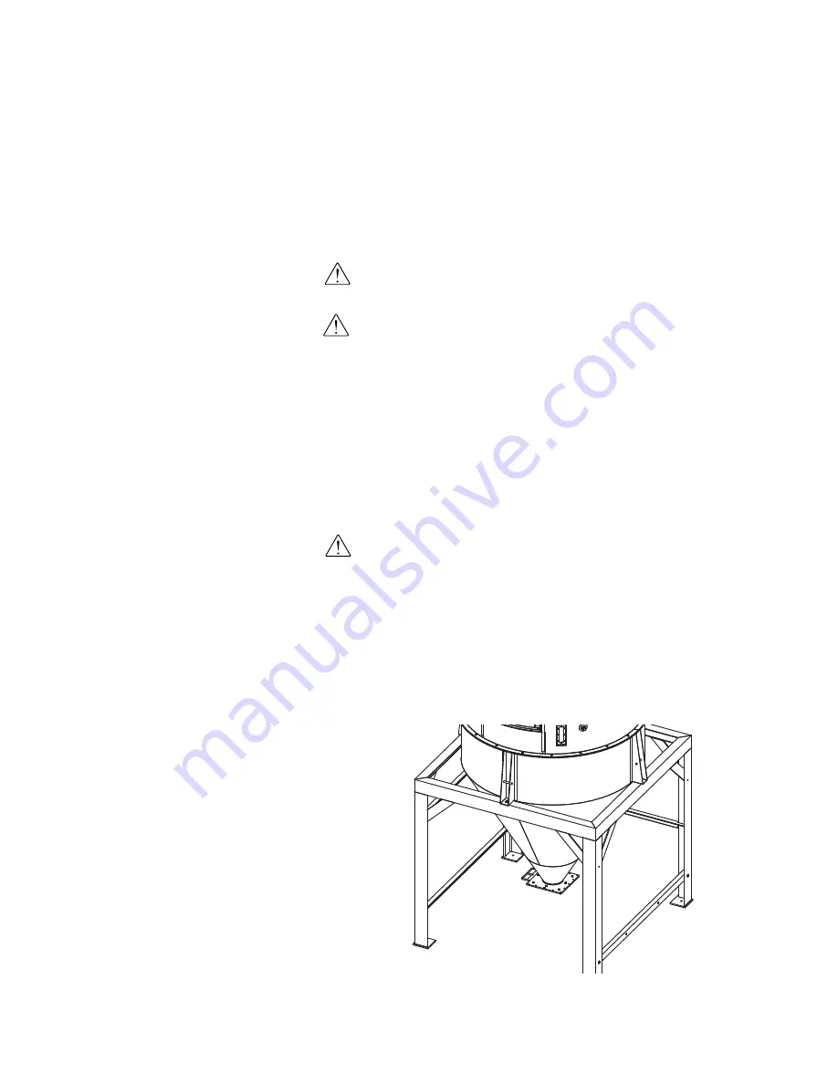
Install the hopper cone section on the floor stand using the following steps.
IMPORTANT:
You will need to consider the location of the CH Hopper’s deliv-
ery air inlet in relation to the dryer installation location for proper setup.
IMPORTANT:
You will need to consider the location of the HTC heater outlet
in relation to the CH Hopper air inlet location for proper setup.
1
If any hoses, wires, etc. were attached to the floor stand and cone
section
(for shipping purposes), make sure they are positioned away
from the mating surfaces of the assemblies so they will not be damaged
during this procedure.
2
Using a forklift, hoist or crane, lift the cone section assembly above
the floor stand.
CAUTION:
To prevent accident and injury, lift the cone and hopper sections
onto the floor stand assembly using a forklift, hoist or crane.
3
Set the cone section on the floor stand as shown.
Make sure the holes
in the cone section mounting lugs align with the holes in the top of the
floor stand assembly.
4
Secure the cone section to the floor stand assembly
using the supplied
hardware.
NOTE:
For EnergySmart Dryer
Systems supplied with "small"
hoppers, the floor stand and cone
section may be pre-assembled at
the factory. If your floor stand
and cone section are pre-assem-
bled and you have secured the
floor stand to the floor,
see
Installation section entitled,
Installing the CH Hopper Door,
Upper and Lid Sections.
✐
3-12
l I n s t a l l a t i o n - G e n e r a l
NOTE:
If using carbon steel hop-
pers, be sure to clean out the
hopper prior to use. Conair
applies a rust inhibitor that must
be removed several hours before
using the hopper.
✐
Содержание HTC 120
Страница 10: ...viii l Table of Contents ...
Страница 30: ...2 14 l Description ...
Страница 35: ...Installation General Installation General l 3 5 3 I n s t a l l a t i o n ...
Страница 65: ...Installation Hard Piping Kits Installation Piping Hoses l 3 35 3 I n s t a l l a t i o n ...
Страница 80: ...3 50 l Installation Piping Hoses ...
Страница 81: ...3 I n s t a l l a t i o n Installation Main Power Connections Installation Main Power Connections l 3 51 ...
Страница 88: ...3 58 l Installation Piping Hoses ...
Страница 89: ...3 I n s t a l l a t i o n Installation Main Power Connections l 3 59 Installation Conveying Lines ...
Страница 92: ...3 62 l Installation Conveying Lines ...
Страница 93: ...Installation Water Lines 3 I n s t a l l a t i o n Installation Water Lines l 3 63 ...
Страница 115: ...Installation Compressed Air Lines 3 I n s t a l l a t i o n Installation Compressed Air Lines l 3 85 ...
Страница 124: ...3 94 l Installation Gas Piping and Exhaust Flue ...
Страница 125: ...Installation Testing 3 I n s t a l l a t i o n Installation Testing l 3 95 ...
Страница 149: ...4 O p e r a t i o n Operation l 4 7 Control Function Flow Charts continued Operation Flow Chart 1 1A 2 3 4 continued 5 ...
Страница 152: ...Control Function Flow Charts continued Setup Flow Chart 1 1B 19 38 20 34 37 4 10 l Operation continued ...
Страница 250: ...4 108 l Operation ...
Страница 286: ...5 36 l Maintenance ...