


NOTE Naming conventions for structural member styles are not fixed. In the case of structural member styles defined as a
result of the Structural Member Catalog, it is acceptable and more efficient in many cases to use the default name that is
provided by the catalog. As an example the “Plywood Web Joist - 10” style name listed above would be “10in Plywood Web
Wood Joist”.
Best Practices for Structural Member Styles:
■
When naming a structural member style, consider whether it can be used for more than one purpose. For example,
wide flange shapes can be used for either columns, bracing or beams. In the case of such an element, you should
not indicate a specific use in the member style name.
■
When defining custom display blocks for the Model display of structural member styles, you should use other
structural members to define the blocks where possible, in lieu of mass elements. An example of this is seen in the
example Bar Joist styles that are provided with AutoCAD Architecture. The custom display blocks that define the
webbing are made from a structural member style called “Steel Joist Webbing”.
■
Materials should be assigned to structural member style components.
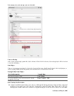
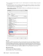
Documentation Objects
AutoCAD Architecture documentation objects are object types that are explicitly for use as annotation tools. Rather
than define 3D geometry, they define data structures and 2D annotation graphics.
NOTE Since documentation objects do not define geometry, it is not necessary to classify their styles for scheduling purposes,
however you may want to consider it if you need more display control than that provided by the normal display set controls.
Sections and Elevations
2D sections and elevations define the 2D representation of orthogonal views of a 3D building model. They are not
geometric objects in and of themselves, but are more of a “report” of the model.
2D Section/Elevation Styles
The purpose of a 2D Section/Elevation style is to automate the display characteristics of linework in the section/elevation
object.
IMPORTANT It is important to have a standardized display system established before creating custom 2D Section/Elevation
styles. The Design Rules of a Section/Elevation style are wholly dependent upon the colors assigned to objects in the display
representation used by the section/elevation object. By default, this is usually an object’s “Model” or “Elevation” display
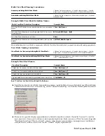
representation. To find out which specific display representation is used by section/elevations for each object type, you can
refer to Display Manager and review the Display Representation Control for the “Section_Elev” display set, or whatever other
display set is specified as part of the section/elevation’s properties.
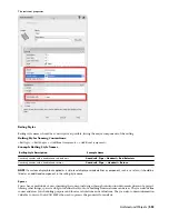
2D Section/Elevation Style Naming Conventions:
<2D Section purpose or use> - <Optional scale>
Example 2D Section/Elevation Style Names:
Example Name
2D Section/Elevation Style Description
Bldg Section-Elevation - 48
A section/elevation style to be used for elevations and sections plotted
at 1/4”=1’-0”.
Detail Background
A section/elevation style for use as a background for a detail view.
Best Practices for 2D Section/Elevation Styles
■
If you define custom components and design rules in your section/elevation style, you should always include a
description. The description for the design rules should explain what action each rule takes in the display properties
of the style. For example, you might have a display component named “Swing Lines”. The component description
would be simply “Door and Window swing lines”. The design rule accompanying the component might have a
description of “Make window and door swings a fine line weight and dashed”.
Documentation Objects | 555
Содержание 00128-051462-9310 - AUTOCAD 2008 COMM UPG FRM 2005 DVD
Страница 1: ...AutoCAD Architecture 2008 User s Guide 2007 ...
Страница 4: ...1 2 3 4 5 6 7 8 9 10 ...
Страница 40: ...xl Contents ...
Страница 41: ...Workflow and User Interface 1 1 ...
Страница 42: ...2 Chapter 1 Workflow and User Interface ...
Страница 146: ...106 Chapter 3 Content Browser ...
Страница 164: ...124 Chapter 4 Creating and Saving Drawings ...
Страница 370: ...330 Chapter 6 Drawing Management ...
Страница 440: ...400 Chapter 8 Drawing Compare ...
Страница 528: ...488 Chapter 10 Display System ...
Страница 540: ...500 Chapter 11 Style Manager ...
Страница 612: ...572 Chapter 13 Content Creation Guidelines ...
Страница 613: ...Conceptual Design 2 573 ...
Страница 614: ...574 Chapter 14 Conceptual Design ...
Страница 678: ...638 Chapter 16 ObjectViewer ...
Страница 683: ...Designing with Architectural Objects 3 643 ...
Страница 684: ...644 Chapter 18 Designing with Architectural Objects ...
Страница 788: ...748 Chapter 18 Walls ...
Страница 942: ...902 Chapter 19 Curtain Walls ...
Страница 1042: ...1002 Chapter 21 AEC Polygons ...
Страница 1052: ...Changing a door width 1012 Chapter 22 Doors ...
Страница 1106: ...Changing a window width 1066 Chapter 23 Windows ...
Страница 1172: ...1132 Chapter 24 Openings ...
Страница 1226: ...Using grips to change the flight width of a spiral stair run 1186 Chapter 25 Stairs ...
Страница 1368: ...Using the Angle grip to edit slab slope 1328 Chapter 28 Slabs and Roof Slabs ...
Страница 1491: ...Design Utilities 4 1451 ...
Страница 1492: ...1452 Chapter 30 Design Utilities ...
Страница 1536: ...1496 Chapter 31 Layout Curves and Grids ...
Страница 1537: ...Grids Grids are AEC objects on which you can anchor other objects such as columns and constrain their locations 32 1497 ...
Страница 1564: ...1524 Chapter 32 Grids ...
Страница 1570: ...Transferring a hatch from one boundary to another Moving a hatch back to original boundary 1530 Chapter 33 Detail Drafting Tools ...
Страница 1611: ...Documentation 5 1571 ...
Страница 1612: ...1572 Chapter 36 Documentation ...
Страница 1706: ...Stretching a surface opening Moving a surface opening 1666 Chapter 36 Spaces ...
Страница 1710: ...Offsetting the edge of a window opening on a freeform space surface 1670 Chapter 36 Spaces ...
Страница 1711: ...Adding a vertex to the edge of a window opening on a freeform space surface Working with Surface Openings 1671 ...
Страница 1712: ...Converting the edge of a window opening to arc on a freeform space surface 1672 Chapter 36 Spaces ...
Страница 1715: ...Removing the vertex of a window opening on a freeform space surface Working with Surface Openings 1675 ...
Страница 1927: ...Elevation Labels Elevation labels are used to dimension height values in plan and section views 41 1887 ...
Страница 1956: ...1916 Chapter 42 Fields ...
Страница 2035: ...Properties of a detail callout The Properties of a Callout Tool 1995 ...
Страница 2060: ...2020 Chapter 45 Callouts ...
Страница 2170: ...2130 Chapter 47 AEC Content and DesignCenter ...
Страница 2171: ...Other Utilities 6 2131 ...
Страница 2172: ...2132 Chapter 48 Other Utilities ...
Страница 2182: ...2142 Chapter 51 Reference AEC Objects ...
Страница 2212: ...2172 Chapter 52 Customizing and Adding New Content for Detail Components ...
Страница 2217: ...AutoCAD Architecture 2008 Menus 54 2177 ...
Страница 2226: ...2186 Chapter 54 AutoCAD Architecture 2008 Menus ...
Страница 2268: ...2228 Index ...


