


TIP After specifying the desired settings, you can move or hide the Properties palette to expose more of the
drawing area.
11
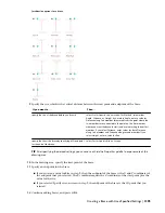
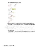
Move the cursor over the grid so that the grid is highlighted and the list of column-add options is displayed.
(You press
Ctrl
to cycle through the options.)
12
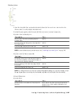
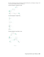
Specify the insert point for the column on the grid.
Then…
If you want to…
move the cursor over the node (or near it), and click. A
column is added to the node nearest to the cursor position.
add a column at a particular node in the grid
press Ctrl, and click.
add a column to all nodes in the grid
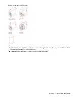
press Ctrl twice, move the cursor to the point where you want
to add the column, and click. If the Properties palette value
for Specify roll on screen is Yes, move the cursor to roll the
column around its extruded axis as desired, and then click;
or enter a value for the roll angle, and press ENTER.
A positive value rolls the column counterclockwise around its
extruded axis when viewed from its end (top) to its start
(bottom).
add a column at a particular point on or within the grid
13
When you are finished adding columns to the grid, press
enter
to end the command.
NOTE Column grids that have numerous columns attached to them can take longer than expected to display
on screen. This is because structural members carry additional information that may be used for structural analysis.
Creating a Structural Member from Linework
Use this procedure to convert any of the following objects to structural members with structural member tools:
■
Arcs
■
Lines
■
Open polylines
■
Open polylines with arc segments
NOTE Converting an arc to a structural member is the only method of creating a curved structural member. For more
information about curved structural members, see
“
About Curved Structural Members
” on page 1412
.
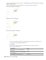
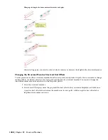
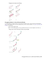
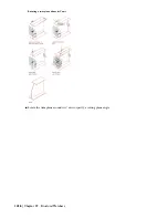
When you use a tool to convert linework to a structural member, the style specified in the tool provides the shape of
the member. The linework defines the extrusion path for the shape. You can convert multiple lines to create multiple
members, convert curved lines to create curved members, and convert multi-segmented lines to create multi-segmented
members.
1
Open the tool palette that contains the structural member tool you want to use.
(You may have to scroll to display the desired tool).
2
Right-click a structural member tool, and click Apply Tool Properties to Linework.
3
Select the linework to convert, and press
ENTER
.
NOTE You cannot convert a closed polyline (a polyline with a start node that coincides with its end node) to a
structural member.
1402 | Chapter 29 Structural Members
Содержание 00128-051462-9310 - AUTOCAD 2008 COMM UPG FRM 2005 DVD
Страница 1: ...AutoCAD Architecture 2008 User s Guide 2007 ...
Страница 4: ...1 2 3 4 5 6 7 8 9 10 ...
Страница 40: ...xl Contents ...
Страница 41: ...Workflow and User Interface 1 1 ...
Страница 42: ...2 Chapter 1 Workflow and User Interface ...
Страница 146: ...106 Chapter 3 Content Browser ...
Страница 164: ...124 Chapter 4 Creating and Saving Drawings ...
Страница 370: ...330 Chapter 6 Drawing Management ...
Страница 440: ...400 Chapter 8 Drawing Compare ...
Страница 528: ...488 Chapter 10 Display System ...
Страница 540: ...500 Chapter 11 Style Manager ...
Страница 612: ...572 Chapter 13 Content Creation Guidelines ...
Страница 613: ...Conceptual Design 2 573 ...
Страница 614: ...574 Chapter 14 Conceptual Design ...
Страница 678: ...638 Chapter 16 ObjectViewer ...
Страница 683: ...Designing with Architectural Objects 3 643 ...
Страница 684: ...644 Chapter 18 Designing with Architectural Objects ...
Страница 788: ...748 Chapter 18 Walls ...
Страница 942: ...902 Chapter 19 Curtain Walls ...
Страница 1042: ...1002 Chapter 21 AEC Polygons ...
Страница 1052: ...Changing a door width 1012 Chapter 22 Doors ...
Страница 1106: ...Changing a window width 1066 Chapter 23 Windows ...
Страница 1172: ...1132 Chapter 24 Openings ...
Страница 1226: ...Using grips to change the flight width of a spiral stair run 1186 Chapter 25 Stairs ...
Страница 1368: ...Using the Angle grip to edit slab slope 1328 Chapter 28 Slabs and Roof Slabs ...
Страница 1491: ...Design Utilities 4 1451 ...
Страница 1492: ...1452 Chapter 30 Design Utilities ...
Страница 1536: ...1496 Chapter 31 Layout Curves and Grids ...
Страница 1537: ...Grids Grids are AEC objects on which you can anchor other objects such as columns and constrain their locations 32 1497 ...
Страница 1564: ...1524 Chapter 32 Grids ...
Страница 1570: ...Transferring a hatch from one boundary to another Moving a hatch back to original boundary 1530 Chapter 33 Detail Drafting Tools ...
Страница 1611: ...Documentation 5 1571 ...
Страница 1612: ...1572 Chapter 36 Documentation ...
Страница 1706: ...Stretching a surface opening Moving a surface opening 1666 Chapter 36 Spaces ...
Страница 1710: ...Offsetting the edge of a window opening on a freeform space surface 1670 Chapter 36 Spaces ...
Страница 1711: ...Adding a vertex to the edge of a window opening on a freeform space surface Working with Surface Openings 1671 ...
Страница 1712: ...Converting the edge of a window opening to arc on a freeform space surface 1672 Chapter 36 Spaces ...
Страница 1715: ...Removing the vertex of a window opening on a freeform space surface Working with Surface Openings 1675 ...
Страница 1927: ...Elevation Labels Elevation labels are used to dimension height values in plan and section views 41 1887 ...
Страница 1956: ...1916 Chapter 42 Fields ...
Страница 2035: ...Properties of a detail callout The Properties of a Callout Tool 1995 ...
Страница 2060: ...2020 Chapter 45 Callouts ...
Страница 2170: ...2130 Chapter 47 AEC Content and DesignCenter ...
Страница 2171: ...Other Utilities 6 2131 ...
Страница 2172: ...2132 Chapter 48 Other Utilities ...
Страница 2182: ...2142 Chapter 51 Reference AEC Objects ...
Страница 2212: ...2172 Chapter 52 Customizing and Adding New Content for Detail Components ...
Страница 2217: ...AutoCAD Architecture 2008 Menus 54 2177 ...
Страница 2226: ...2186 Chapter 54 AutoCAD Architecture 2008 Menus ...
Страница 2268: ...2228 Index ...


