


Then…
If you want to…
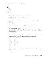
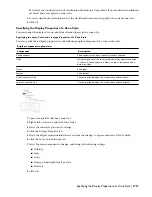
enter a value for Column Offset.
define the offset between columns of the zone structure
5
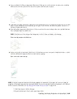
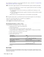
In the drawing area, specify the insertion point of the zone structure.
You can move or hide the Properties palette to expose more of the drawing area.
6
Continue adding zone structures from the template as needed, and then press
ENTER
.
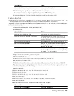
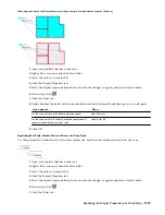
Creating a Zone Tool
Use this procedure to create a zone tool and add it to a tool palette. You may want to create your own zone tools if you
are placing multiple zones with specific properties that you want to be the same for each instance.
For example, if you are creating an office floor plan with different calculation types for zones, you can create a zone
tool for each calculation type.
1
Open the tool palette where you want to create a tool.
2
Create the tool:
Then…
If you want to…
select the zone, and drag it to the tool palette.
create a tool from a zone in the drawing
click Format menu
➤
Style Manager. Locate the style you
want to copy, and drag it to the tool palette. Click OK to
close the Style Manager.
create a tool from an zone style in the Style Manager
right-click the tool, and click Copy. Right-click, and click Paste.
copy a tool in the current tool palette
open the other tool palette, right-click the tool, and click
Copy. Reopen the palette where you want to add the tool,
right-click, and click Paste.
copy a tool from another tool palette
open the catalog in the Content Browser, and locate the tool
you want to copy. Position the cursor over the i-drop handle,
and drag the tool to the tool palette.
copy a tool from a tool catalog
3
Right-click the new zone tool, and click Properties.
4
Enter a name for the tool.
5
Click the setting for Description, enter a description of the tool, and click OK.
6
Expand Basic, and expand General.
7
Click the setting for Description, enter a description of the zone created from this tool, and click OK.
8
Specify a layer key and any layer key overrides if you do not want to use the layer assignments specified
in the layer key style used in the drawing.
9
Select a zone style.
10
Select the drawing file containing the style used for this zone tool.
11
Select a tag for the zone.
12
Select the drawing file containing the tag used for this zone tool.
13
Expand Dimensions.
14
Enter the distance you want the zone boundary to be offset from attached spaces.
15
Expand Calculation.
16
Specify which values will be calculated for zones created from this tool:
Then…
If you want to …
select Yes for Calculate Area.
calculate the area of attached spaces
Creating a Zone Tool | 1703
Содержание 00128-051462-9310 - AUTOCAD 2008 COMM UPG FRM 2005 DVD
Страница 1: ...AutoCAD Architecture 2008 User s Guide 2007 ...
Страница 4: ...1 2 3 4 5 6 7 8 9 10 ...
Страница 40: ...xl Contents ...
Страница 41: ...Workflow and User Interface 1 1 ...
Страница 42: ...2 Chapter 1 Workflow and User Interface ...
Страница 146: ...106 Chapter 3 Content Browser ...
Страница 164: ...124 Chapter 4 Creating and Saving Drawings ...
Страница 370: ...330 Chapter 6 Drawing Management ...
Страница 440: ...400 Chapter 8 Drawing Compare ...
Страница 528: ...488 Chapter 10 Display System ...
Страница 540: ...500 Chapter 11 Style Manager ...
Страница 612: ...572 Chapter 13 Content Creation Guidelines ...
Страница 613: ...Conceptual Design 2 573 ...
Страница 614: ...574 Chapter 14 Conceptual Design ...
Страница 678: ...638 Chapter 16 ObjectViewer ...
Страница 683: ...Designing with Architectural Objects 3 643 ...
Страница 684: ...644 Chapter 18 Designing with Architectural Objects ...
Страница 788: ...748 Chapter 18 Walls ...
Страница 942: ...902 Chapter 19 Curtain Walls ...
Страница 1042: ...1002 Chapter 21 AEC Polygons ...
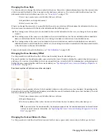
Страница 1052: ...Changing a door width 1012 Chapter 22 Doors ...
Страница 1106: ...Changing a window width 1066 Chapter 23 Windows ...
Страница 1172: ...1132 Chapter 24 Openings ...
Страница 1226: ...Using grips to change the flight width of a spiral stair run 1186 Chapter 25 Stairs ...
Страница 1368: ...Using the Angle grip to edit slab slope 1328 Chapter 28 Slabs and Roof Slabs ...
Страница 1491: ...Design Utilities 4 1451 ...
Страница 1492: ...1452 Chapter 30 Design Utilities ...
Страница 1536: ...1496 Chapter 31 Layout Curves and Grids ...
Страница 1537: ...Grids Grids are AEC objects on which you can anchor other objects such as columns and constrain their locations 32 1497 ...
Страница 1564: ...1524 Chapter 32 Grids ...
Страница 1570: ...Transferring a hatch from one boundary to another Moving a hatch back to original boundary 1530 Chapter 33 Detail Drafting Tools ...
Страница 1611: ...Documentation 5 1571 ...
Страница 1612: ...1572 Chapter 36 Documentation ...
Страница 1706: ...Stretching a surface opening Moving a surface opening 1666 Chapter 36 Spaces ...
Страница 1710: ...Offsetting the edge of a window opening on a freeform space surface 1670 Chapter 36 Spaces ...
Страница 1711: ...Adding a vertex to the edge of a window opening on a freeform space surface Working with Surface Openings 1671 ...
Страница 1712: ...Converting the edge of a window opening to arc on a freeform space surface 1672 Chapter 36 Spaces ...
Страница 1715: ...Removing the vertex of a window opening on a freeform space surface Working with Surface Openings 1675 ...
Страница 1927: ...Elevation Labels Elevation labels are used to dimension height values in plan and section views 41 1887 ...
Страница 1956: ...1916 Chapter 42 Fields ...
Страница 2035: ...Properties of a detail callout The Properties of a Callout Tool 1995 ...
Страница 2060: ...2020 Chapter 45 Callouts ...
Страница 2170: ...2130 Chapter 47 AEC Content and DesignCenter ...
Страница 2171: ...Other Utilities 6 2131 ...
Страница 2172: ...2132 Chapter 48 Other Utilities ...
Страница 2182: ...2142 Chapter 51 Reference AEC Objects ...
Страница 2212: ...2172 Chapter 52 Customizing and Adding New Content for Detail Components ...
Страница 2217: ...AutoCAD Architecture 2008 Menus 54 2177 ...
Страница 2226: ...2186 Chapter 54 AutoCAD Architecture 2008 Menus ...
Страница 2268: ...2228 Index ...