


Introduction to the Display System
The display system in AutoCAD Architecture is designed so that you only have to draw an architectural object once.
The appearance of that object then changes automatically to meet the display requirements of different types of
drawings, view directions, or levels of detail.
Display Properties and Display Components
The view-dependent display of objects in AutoCAD Architecture is made possible by a hierarchical system of display
settings that specify display properties (visibility, layer, color, linetype, and so on) for individual display components
of all the different types of architectural objects under all the different viewing scenarios.
For example, a door object has 5 display components by default: Door Panel, Frame, Stop, Swing, and Glass. (Many
display components correspond directly to the physical components of the object, but some, like Swing, do not.) For
each of these display components, the drawing default settings specify the relevant display properties as appropriate
for the drawing type. In the case of doors, the default settings specify that the Swing component is visible in plan and
elevation views, but not in 3D views.
Overrides
The drawing default settings for a particular type of object apply to all such objects in the drawing, except those for
which an override is in effect. For example, you can change a setting for all doors of a particular style (a style override)
or for an individual door (an object override).
Establishing and Modifying Default Display Settings
If you are a CAD manager, you will want to fully understand the “
Display System Structure
” on page 450 and “
The
Display Manager
” on page 457 topics so that you can modify and organize default settings as necessary to implement
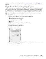
your own display standards. But any user can quickly change the appearance of an object in a particular view by
modifying values on the Display tab of the Properties palette.
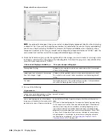
NOTE To hide the Display Tab (or show it if it is currently hidden), enter the following command at the command line:
AecChangeDisplayTabStatus.
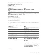
Display tab when display component is selected
To change the display using this tab, you select an object display component (like a hatch or a boundary), and then
select or enter a new value for the display property you want to change (such as color, visibility, or lineweight). The
results are immediately visible in the drawing area for the current display representation and can be applied to other
444 | Chapter 10 Display System
Содержание 00128-051462-9310 - AUTOCAD 2008 COMM UPG FRM 2005 DVD
Страница 1: ...AutoCAD Architecture 2008 User s Guide 2007 ...
Страница 4: ...1 2 3 4 5 6 7 8 9 10 ...
Страница 40: ...xl Contents ...
Страница 41: ...Workflow and User Interface 1 1 ...
Страница 42: ...2 Chapter 1 Workflow and User Interface ...
Страница 146: ...106 Chapter 3 Content Browser ...
Страница 164: ...124 Chapter 4 Creating and Saving Drawings ...
Страница 370: ...330 Chapter 6 Drawing Management ...
Страница 440: ...400 Chapter 8 Drawing Compare ...
Страница 528: ...488 Chapter 10 Display System ...
Страница 540: ...500 Chapter 11 Style Manager ...
Страница 612: ...572 Chapter 13 Content Creation Guidelines ...
Страница 613: ...Conceptual Design 2 573 ...
Страница 614: ...574 Chapter 14 Conceptual Design ...
Страница 678: ...638 Chapter 16 ObjectViewer ...
Страница 683: ...Designing with Architectural Objects 3 643 ...
Страница 684: ...644 Chapter 18 Designing with Architectural Objects ...
Страница 788: ...748 Chapter 18 Walls ...
Страница 942: ...902 Chapter 19 Curtain Walls ...
Страница 1042: ...1002 Chapter 21 AEC Polygons ...
Страница 1052: ...Changing a door width 1012 Chapter 22 Doors ...
Страница 1106: ...Changing a window width 1066 Chapter 23 Windows ...
Страница 1172: ...1132 Chapter 24 Openings ...
Страница 1226: ...Using grips to change the flight width of a spiral stair run 1186 Chapter 25 Stairs ...
Страница 1368: ...Using the Angle grip to edit slab slope 1328 Chapter 28 Slabs and Roof Slabs ...
Страница 1491: ...Design Utilities 4 1451 ...
Страница 1492: ...1452 Chapter 30 Design Utilities ...
Страница 1536: ...1496 Chapter 31 Layout Curves and Grids ...
Страница 1537: ...Grids Grids are AEC objects on which you can anchor other objects such as columns and constrain their locations 32 1497 ...
Страница 1564: ...1524 Chapter 32 Grids ...
Страница 1570: ...Transferring a hatch from one boundary to another Moving a hatch back to original boundary 1530 Chapter 33 Detail Drafting Tools ...
Страница 1611: ...Documentation 5 1571 ...
Страница 1612: ...1572 Chapter 36 Documentation ...
Страница 1706: ...Stretching a surface opening Moving a surface opening 1666 Chapter 36 Spaces ...
Страница 1710: ...Offsetting the edge of a window opening on a freeform space surface 1670 Chapter 36 Spaces ...
Страница 1711: ...Adding a vertex to the edge of a window opening on a freeform space surface Working with Surface Openings 1671 ...
Страница 1712: ...Converting the edge of a window opening to arc on a freeform space surface 1672 Chapter 36 Spaces ...
Страница 1715: ...Removing the vertex of a window opening on a freeform space surface Working with Surface Openings 1675 ...
Страница 1927: ...Elevation Labels Elevation labels are used to dimension height values in plan and section views 41 1887 ...
Страница 1956: ...1916 Chapter 42 Fields ...
Страница 2035: ...Properties of a detail callout The Properties of a Callout Tool 1995 ...
Страница 2060: ...2020 Chapter 45 Callouts ...
Страница 2170: ...2130 Chapter 47 AEC Content and DesignCenter ...
Страница 2171: ...Other Utilities 6 2131 ...
Страница 2172: ...2132 Chapter 48 Other Utilities ...
Страница 2182: ...2142 Chapter 51 Reference AEC Objects ...
Страница 2212: ...2172 Chapter 52 Customizing and Adding New Content for Detail Components ...
Страница 2217: ...AutoCAD Architecture 2008 Menus 54 2177 ...
Страница 2226: ...2186 Chapter 54 AutoCAD Architecture 2008 Menus ...
Страница 2268: ...2228 Index ...


