


7
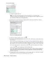
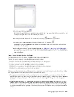
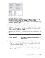
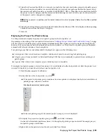
To define that a specific style type should be controlled by a specific standards drawing, click the style
type’s check box in the appropriate drawing column.
TIP If you want to select one drawing for all style types, right-click in the header, and click Select Column.
If a style type has not been associated with a standards drawing, these styles are not controlled by the
standards. For example, if the standards drawing “Standard Styles 1.dwg” has not been associated with the
Wall Styles type, then even if wall styles from this standards drawing exist in a project drawing, they will
be interpreted as “not standardized” by the synchronization.
If you select multiple standards drawings for one style type, then during synchronization, each drawing is
searched for that style type in the order of the drawings. This means that you can distribute standard styles
for a style type among different drawings. For example, you could store your concrete wall styles in the
standards drawing “Wall Styles - Concrete (Imperial)”, and your brick wall styles in the drawing “Wall
Styles - Brick (Imperial)”.
NOTE If two standards drawings contain a style of the same name and type, the style in the first standards
drawing will be used for synchronization. Further instances of that style will be ignored. The order of standards
drawings is determined by their position from left to right in the table. To re-order the drawings, use the Up
and Down
buttons.
8
To remove a standard styles drawing from the project, click on its name in the Standards Drawings list,
and click
.
Removing a standards drawing from the list only removes the reference of this drawing to the project. The
drawing is not deleted from the file system.
Next, you need to define a standards drawings for the display settings in the project. You can assign only
one standards drawing for display settings. The standard display settings drawing can be one already
assigned as a styles standards drawing.
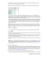
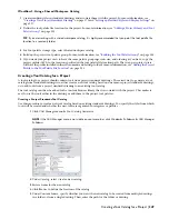
9
Under Select drawing to use for standard display settings, select a file. If necessary, select Browse to browse
for a file.
NOTE If you are using a display standards drawing that is different from the styles standards drawing, or if you
have multiple styles standards drawings, you need to make sure that the styles standard drawings are in synch
with the display standards drawing. For more information, see
“
Synchronizing Project Standards with Each
Other
” on page 382
.
10
Click the Synchronization tab.
If you have added a standards drawing to the project, and the drawing is located in the project folder, the
drawing will automatically have initial version information added to all styles and display settings. If the
new standards drawing is located outside the project folder, and has not yet been versioned, you need to
version it as described in “
Versioning a Project Standards Drawing
” on page 380. For more information
about versioning, see “
Versioning Standards
” on page 373.
11
If necessary, enter a universal comment to all versioned styles and display settings.
For instance, you might want to add a comment to indicate what has changed in the style as of this version.
Configuring Project Standards | 339
Содержание 00128-051462-9310 - AUTOCAD 2008 COMM UPG FRM 2005 DVD
Страница 1: ...AutoCAD Architecture 2008 User s Guide 2007 ...
Страница 4: ...1 2 3 4 5 6 7 8 9 10 ...
Страница 40: ...xl Contents ...
Страница 41: ...Workflow and User Interface 1 1 ...
Страница 42: ...2 Chapter 1 Workflow and User Interface ...
Страница 146: ...106 Chapter 3 Content Browser ...
Страница 164: ...124 Chapter 4 Creating and Saving Drawings ...
Страница 370: ...330 Chapter 6 Drawing Management ...
Страница 440: ...400 Chapter 8 Drawing Compare ...
Страница 528: ...488 Chapter 10 Display System ...
Страница 540: ...500 Chapter 11 Style Manager ...
Страница 612: ...572 Chapter 13 Content Creation Guidelines ...
Страница 613: ...Conceptual Design 2 573 ...
Страница 614: ...574 Chapter 14 Conceptual Design ...
Страница 678: ...638 Chapter 16 ObjectViewer ...
Страница 683: ...Designing with Architectural Objects 3 643 ...
Страница 684: ...644 Chapter 18 Designing with Architectural Objects ...
Страница 788: ...748 Chapter 18 Walls ...
Страница 942: ...902 Chapter 19 Curtain Walls ...
Страница 1042: ...1002 Chapter 21 AEC Polygons ...
Страница 1052: ...Changing a door width 1012 Chapter 22 Doors ...
Страница 1106: ...Changing a window width 1066 Chapter 23 Windows ...
Страница 1172: ...1132 Chapter 24 Openings ...
Страница 1226: ...Using grips to change the flight width of a spiral stair run 1186 Chapter 25 Stairs ...
Страница 1368: ...Using the Angle grip to edit slab slope 1328 Chapter 28 Slabs and Roof Slabs ...
Страница 1491: ...Design Utilities 4 1451 ...
Страница 1492: ...1452 Chapter 30 Design Utilities ...
Страница 1536: ...1496 Chapter 31 Layout Curves and Grids ...
Страница 1537: ...Grids Grids are AEC objects on which you can anchor other objects such as columns and constrain their locations 32 1497 ...
Страница 1564: ...1524 Chapter 32 Grids ...
Страница 1570: ...Transferring a hatch from one boundary to another Moving a hatch back to original boundary 1530 Chapter 33 Detail Drafting Tools ...
Страница 1611: ...Documentation 5 1571 ...
Страница 1612: ...1572 Chapter 36 Documentation ...
Страница 1706: ...Stretching a surface opening Moving a surface opening 1666 Chapter 36 Spaces ...
Страница 1710: ...Offsetting the edge of a window opening on a freeform space surface 1670 Chapter 36 Spaces ...
Страница 1711: ...Adding a vertex to the edge of a window opening on a freeform space surface Working with Surface Openings 1671 ...
Страница 1712: ...Converting the edge of a window opening to arc on a freeform space surface 1672 Chapter 36 Spaces ...
Страница 1715: ...Removing the vertex of a window opening on a freeform space surface Working with Surface Openings 1675 ...
Страница 1927: ...Elevation Labels Elevation labels are used to dimension height values in plan and section views 41 1887 ...
Страница 1956: ...1916 Chapter 42 Fields ...
Страница 2035: ...Properties of a detail callout The Properties of a Callout Tool 1995 ...
Страница 2060: ...2020 Chapter 45 Callouts ...
Страница 2170: ...2130 Chapter 47 AEC Content and DesignCenter ...
Страница 2171: ...Other Utilities 6 2131 ...
Страница 2172: ...2132 Chapter 48 Other Utilities ...
Страница 2182: ...2142 Chapter 51 Reference AEC Objects ...
Страница 2212: ...2172 Chapter 52 Customizing and Adding New Content for Detail Components ...
Страница 2217: ...AutoCAD Architecture 2008 Menus 54 2177 ...
Страница 2226: ...2186 Chapter 54 AutoCAD Architecture 2008 Menus ...
Страница 2268: ...2228 Index ...


