
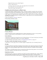

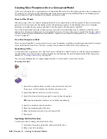


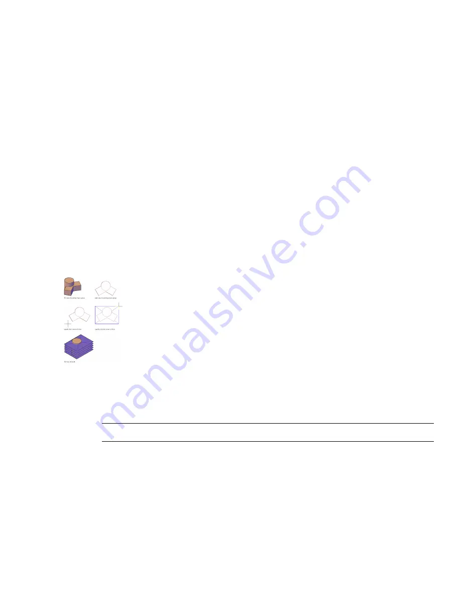
Creating Slice Floorplates from a Conceptual Model
A slice can be thought of as a representation of a theoretical floor level. Slice floorplates provide a way to translate the
3D geometry of a mass group into something that can be used to generate the individual floors of a building. Slices
can be converted to space boundaries or polylines, and then to walls.
Slices and Mass Models
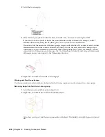
Like mass groups, slices are chosen and manipulated by an associated marker, the slice marker. When you attach mass
groups to the slice marker, the slice marker creates the perimeter geometry of the building, known as a floorplate.
Anytime you change the mass groups attached to the slice marker, the floorplate is updated.
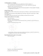
If you attach mass elements instead of mass groups to the slice, the operational aspects (additive, subtractive, and
intersection) of the mass elements are not recognized by the slice. To have these aspects recorded by the slice, attach
the mass group. For more information about additive, subtractive, and intersection operations, see “
Creating a Mass
Group
” on page 627.
From Slice Floorplate to Walls
After you create floorplates, you can convert slices to space boundaries or polylines, and then generate walls. You cannot
create walls directly from a slice. The slice is simply a way to mark each floor level of the mass group.
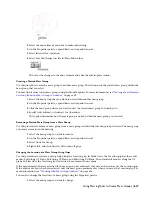
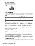
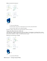
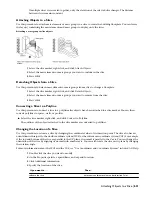
Generating a Slice
Use this procedure to generate a slice. The slice object is defined by a small crossed box. Like the mass group marker,
the slice marker can be located in a convenient place in your drawing. For more information about the mass group
marker, see “
Creating a Mass Group
” on page 627.
You can create multiple slices at regular height intervals. A slice marker is created for each slice.
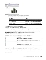
Generating slice objects
1
Open the tool palette that you want to use, and select a slice tool.
If necessary, scroll to display the tool that you want to use.
2
Specify the number of slices you want to create.
3
Specify the lower-left and upper-right corners for the slice marker.
TIP Keep the slice marker small so as not to clutter your drawing.
4
Specify a rotation for the slice marker.
5
Enter the starting height of the slice.
6
Enter the distance between slices, and press
ENTER
.
7
Press
ENTER
.
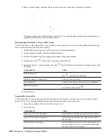
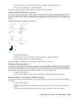
Specifying the Slice Elevation
Use this procedure to change the elevation of a slice.
1
Select the slice marker, right-click, and click Set Elevation.
2
Enter a new slice elevation.
630 | Chapter 14 Creating Conceptual Models
Содержание 00128-051462-9310 - AUTOCAD 2008 COMM UPG FRM 2005 DVD
Страница 1: ...AutoCAD Architecture 2008 User s Guide 2007 ...
Страница 4: ...1 2 3 4 5 6 7 8 9 10 ...
Страница 40: ...xl Contents ...
Страница 41: ...Workflow and User Interface 1 1 ...
Страница 42: ...2 Chapter 1 Workflow and User Interface ...
Страница 146: ...106 Chapter 3 Content Browser ...
Страница 164: ...124 Chapter 4 Creating and Saving Drawings ...
Страница 370: ...330 Chapter 6 Drawing Management ...
Страница 440: ...400 Chapter 8 Drawing Compare ...
Страница 528: ...488 Chapter 10 Display System ...
Страница 540: ...500 Chapter 11 Style Manager ...
Страница 612: ...572 Chapter 13 Content Creation Guidelines ...
Страница 613: ...Conceptual Design 2 573 ...
Страница 614: ...574 Chapter 14 Conceptual Design ...
Страница 678: ...638 Chapter 16 ObjectViewer ...
Страница 683: ...Designing with Architectural Objects 3 643 ...
Страница 684: ...644 Chapter 18 Designing with Architectural Objects ...
Страница 788: ...748 Chapter 18 Walls ...
Страница 942: ...902 Chapter 19 Curtain Walls ...
Страница 1042: ...1002 Chapter 21 AEC Polygons ...
Страница 1052: ...Changing a door width 1012 Chapter 22 Doors ...
Страница 1106: ...Changing a window width 1066 Chapter 23 Windows ...
Страница 1172: ...1132 Chapter 24 Openings ...
Страница 1226: ...Using grips to change the flight width of a spiral stair run 1186 Chapter 25 Stairs ...
Страница 1368: ...Using the Angle grip to edit slab slope 1328 Chapter 28 Slabs and Roof Slabs ...
Страница 1491: ...Design Utilities 4 1451 ...
Страница 1492: ...1452 Chapter 30 Design Utilities ...
Страница 1536: ...1496 Chapter 31 Layout Curves and Grids ...
Страница 1537: ...Grids Grids are AEC objects on which you can anchor other objects such as columns and constrain their locations 32 1497 ...
Страница 1564: ...1524 Chapter 32 Grids ...
Страница 1570: ...Transferring a hatch from one boundary to another Moving a hatch back to original boundary 1530 Chapter 33 Detail Drafting Tools ...
Страница 1611: ...Documentation 5 1571 ...
Страница 1612: ...1572 Chapter 36 Documentation ...
Страница 1706: ...Stretching a surface opening Moving a surface opening 1666 Chapter 36 Spaces ...
Страница 1710: ...Offsetting the edge of a window opening on a freeform space surface 1670 Chapter 36 Spaces ...
Страница 1711: ...Adding a vertex to the edge of a window opening on a freeform space surface Working with Surface Openings 1671 ...
Страница 1712: ...Converting the edge of a window opening to arc on a freeform space surface 1672 Chapter 36 Spaces ...
Страница 1715: ...Removing the vertex of a window opening on a freeform space surface Working with Surface Openings 1675 ...
Страница 1927: ...Elevation Labels Elevation labels are used to dimension height values in plan and section views 41 1887 ...
Страница 1956: ...1916 Chapter 42 Fields ...
Страница 2035: ...Properties of a detail callout The Properties of a Callout Tool 1995 ...
Страница 2060: ...2020 Chapter 45 Callouts ...
Страница 2170: ...2130 Chapter 47 AEC Content and DesignCenter ...
Страница 2171: ...Other Utilities 6 2131 ...
Страница 2172: ...2132 Chapter 48 Other Utilities ...
Страница 2182: ...2142 Chapter 51 Reference AEC Objects ...
Страница 2212: ...2172 Chapter 52 Customizing and Adding New Content for Detail Components ...
Страница 2217: ...AutoCAD Architecture 2008 Menus 54 2177 ...
Страница 2226: ...2186 Chapter 54 AutoCAD Architecture 2008 Menus ...
Страница 2268: ...2228 Index ...


