


The selected display setting is listed in the top panel.
5
To update the project standards from the project drawing, select Update Project Standards from the Action
drop-down list of the display settings.
6
To not update the project standards from the display setting in the project drawing, select Do not Update
Project Standards from the Action drop-down list of the display settings.
In this case, the version in the project standards drawing is not overwritten with the version in the project
drawing. During the next synchronization of the project drawing, the display setting will be displayed as
out of synch with the project standards.
7
To ignore the out of synch version of the display setting, select Ignore from the Action drop-down list.
In this case, the item will not be displayed in future updates, except when you select Show objects set to
ignore during project standards synchronization or remove the Ignore flag from the display setting in
Display Manager, as described in “
Excluding Display Settings from Synchronization
” on page 480.
8
Click OK.
9
In Display Manager, click OK or Apply.
10
Click Yes to save the updated project standards drawing.
Adding Standard Display Settings from a Project Drawing to a Project Standards Drawing
You can add not standardized display settings from the current project drawing to the project standards. You can do
this, for example, if you have created a complex display configuration in a project drawing and want to include that
into your standards.
After copying a display setting to the project standards, you need to synchronize the project to use the new standard
setting.
1
Open a project drawing from Project Navigator.
2
On the Format menu, click Display Manager.
3
Add a new display setting to the current project drawing.
4
Select the new setting, right-click, and click Update Standards from Drawing.
NOTE You can select multiple display settings here.
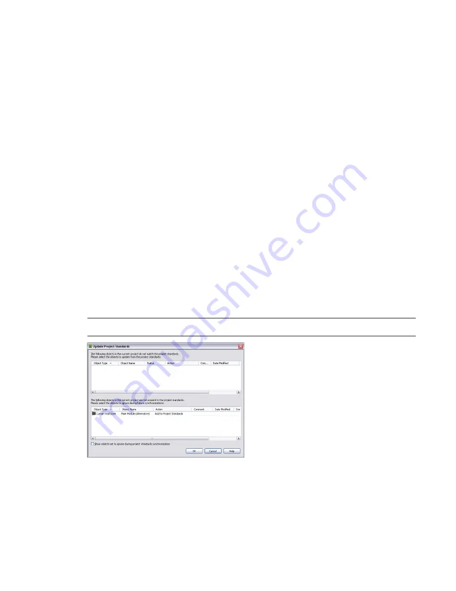
The new setting is listed in the lower panel, which displays styles and display settings in the project drawing
that do not exist in the project standards.
5
To add the display setting to a project standards drawing, and thereby make it a standard setting, select
Add to Project Standards in the Action drop-down list.
6
To skip over the not standardized display setting, select Skip from the Action drop-down list.
In this case, the not standardized display setting remains in the project drawing, and is not entered in the
standards.
Adding Standard Display Settings from a Project Drawing to a Project Standards Drawing | 483
Содержание 00128-051462-9310 - AUTOCAD 2008 COMM UPG FRM 2005 DVD
Страница 1: ...AutoCAD Architecture 2008 User s Guide 2007 ...
Страница 4: ...1 2 3 4 5 6 7 8 9 10 ...
Страница 40: ...xl Contents ...
Страница 41: ...Workflow and User Interface 1 1 ...
Страница 42: ...2 Chapter 1 Workflow and User Interface ...
Страница 146: ...106 Chapter 3 Content Browser ...
Страница 164: ...124 Chapter 4 Creating and Saving Drawings ...
Страница 370: ...330 Chapter 6 Drawing Management ...
Страница 440: ...400 Chapter 8 Drawing Compare ...
Страница 528: ...488 Chapter 10 Display System ...
Страница 540: ...500 Chapter 11 Style Manager ...
Страница 612: ...572 Chapter 13 Content Creation Guidelines ...
Страница 613: ...Conceptual Design 2 573 ...
Страница 614: ...574 Chapter 14 Conceptual Design ...
Страница 678: ...638 Chapter 16 ObjectViewer ...
Страница 683: ...Designing with Architectural Objects 3 643 ...
Страница 684: ...644 Chapter 18 Designing with Architectural Objects ...
Страница 788: ...748 Chapter 18 Walls ...
Страница 942: ...902 Chapter 19 Curtain Walls ...
Страница 1042: ...1002 Chapter 21 AEC Polygons ...
Страница 1052: ...Changing a door width 1012 Chapter 22 Doors ...
Страница 1106: ...Changing a window width 1066 Chapter 23 Windows ...
Страница 1172: ...1132 Chapter 24 Openings ...
Страница 1226: ...Using grips to change the flight width of a spiral stair run 1186 Chapter 25 Stairs ...
Страница 1368: ...Using the Angle grip to edit slab slope 1328 Chapter 28 Slabs and Roof Slabs ...
Страница 1491: ...Design Utilities 4 1451 ...
Страница 1492: ...1452 Chapter 30 Design Utilities ...
Страница 1536: ...1496 Chapter 31 Layout Curves and Grids ...
Страница 1537: ...Grids Grids are AEC objects on which you can anchor other objects such as columns and constrain their locations 32 1497 ...
Страница 1564: ...1524 Chapter 32 Grids ...
Страница 1570: ...Transferring a hatch from one boundary to another Moving a hatch back to original boundary 1530 Chapter 33 Detail Drafting Tools ...
Страница 1611: ...Documentation 5 1571 ...
Страница 1612: ...1572 Chapter 36 Documentation ...
Страница 1706: ...Stretching a surface opening Moving a surface opening 1666 Chapter 36 Spaces ...
Страница 1710: ...Offsetting the edge of a window opening on a freeform space surface 1670 Chapter 36 Spaces ...
Страница 1711: ...Adding a vertex to the edge of a window opening on a freeform space surface Working with Surface Openings 1671 ...
Страница 1712: ...Converting the edge of a window opening to arc on a freeform space surface 1672 Chapter 36 Spaces ...
Страница 1715: ...Removing the vertex of a window opening on a freeform space surface Working with Surface Openings 1675 ...
Страница 1927: ...Elevation Labels Elevation labels are used to dimension height values in plan and section views 41 1887 ...
Страница 1956: ...1916 Chapter 42 Fields ...
Страница 2035: ...Properties of a detail callout The Properties of a Callout Tool 1995 ...
Страница 2060: ...2020 Chapter 45 Callouts ...
Страница 2170: ...2130 Chapter 47 AEC Content and DesignCenter ...
Страница 2171: ...Other Utilities 6 2131 ...
Страница 2172: ...2132 Chapter 48 Other Utilities ...
Страница 2182: ...2142 Chapter 51 Reference AEC Objects ...
Страница 2212: ...2172 Chapter 52 Customizing and Adding New Content for Detail Components ...
Страница 2217: ...AutoCAD Architecture 2008 Menus 54 2177 ...
Страница 2226: ...2186 Chapter 54 AutoCAD Architecture 2008 Menus ...
Страница 2268: ...2228 Index ...


