


12
Enter 1 for Node.
Node 1 corresponds to the vertex formed by the endpoint of the first segment of the member path and
the start point of the second segment of the member path.
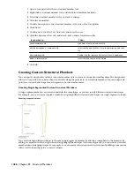
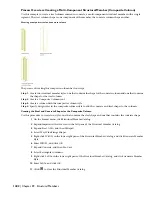
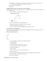
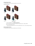
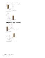
Creating the First Rafter of the Rigid Frame
Use this procedure to create the first rafter of the rigid frame by assigning a different start and end shape to the second
segment of the rigid frame member.
Creating the first rafter of the rigid frame
1
Click Add to add a second component to the structural member.
2
Select Unnamed under Component, and enter Rafter 1.
3
Under Start Shape, in the Name list, select W14X43.
4
Select Start for Relative to.
5
Enter 1 for Node.
6
Scroll to the end of the Design Rules dialog box to display the End Shape parameters for Rafter 1.
7
Under End Shape, in the Name list, select W8X31.
8
Select Start for Relative to.
9
Enter 2 for Node.
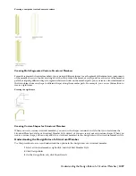
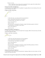
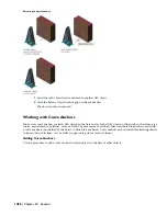
Creating the Second Rafter of the Rigid Frame
Use this procedure to create the second rafter of the rigid frame by assigning a different start and end shape to the third
segment of the rigid frame member.
Creating the second rafter of the rigid frame
1
Click Add to add a third component to the structural member.
2
Select Unnamed under Component, and enter Rafter 2.
3
Under Start Shape, in the Name list, select W8X31.
4
Select Start for Relative to.
5
Enter 2 for Node.
6
Scroll to the end of the Design Rules dialog box to display the End Shape parameters for Rafter 2.
7
Under End Shape, in the Name list, select W14X43.
8
Select Start for Relative to.
9
Enter 3 for Node.
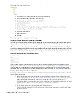
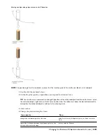
Creating the Second Leg of the Rigid Frame
Use this procedure to create the second leg of the rigid frame by assigning a different start and end shape to the final
segment of the rigid frame member.
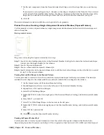
Process Overview: Creating a Multi-Component Structural Member Using Multiple Segments (Rigid Frame) | 1447
Содержание 00128-051462-9310 - AUTOCAD 2008 COMM UPG FRM 2005 DVD
Страница 1: ...AutoCAD Architecture 2008 User s Guide 2007 ...
Страница 4: ...1 2 3 4 5 6 7 8 9 10 ...
Страница 40: ...xl Contents ...
Страница 41: ...Workflow and User Interface 1 1 ...
Страница 42: ...2 Chapter 1 Workflow and User Interface ...
Страница 146: ...106 Chapter 3 Content Browser ...
Страница 164: ...124 Chapter 4 Creating and Saving Drawings ...
Страница 370: ...330 Chapter 6 Drawing Management ...
Страница 440: ...400 Chapter 8 Drawing Compare ...
Страница 528: ...488 Chapter 10 Display System ...
Страница 540: ...500 Chapter 11 Style Manager ...
Страница 612: ...572 Chapter 13 Content Creation Guidelines ...
Страница 613: ...Conceptual Design 2 573 ...
Страница 614: ...574 Chapter 14 Conceptual Design ...
Страница 678: ...638 Chapter 16 ObjectViewer ...
Страница 683: ...Designing with Architectural Objects 3 643 ...
Страница 684: ...644 Chapter 18 Designing with Architectural Objects ...
Страница 788: ...748 Chapter 18 Walls ...
Страница 942: ...902 Chapter 19 Curtain Walls ...
Страница 1042: ...1002 Chapter 21 AEC Polygons ...
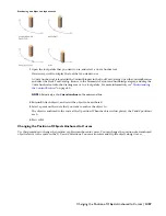
Страница 1052: ...Changing a door width 1012 Chapter 22 Doors ...
Страница 1106: ...Changing a window width 1066 Chapter 23 Windows ...
Страница 1172: ...1132 Chapter 24 Openings ...
Страница 1226: ...Using grips to change the flight width of a spiral stair run 1186 Chapter 25 Stairs ...
Страница 1368: ...Using the Angle grip to edit slab slope 1328 Chapter 28 Slabs and Roof Slabs ...
Страница 1491: ...Design Utilities 4 1451 ...
Страница 1492: ...1452 Chapter 30 Design Utilities ...
Страница 1536: ...1496 Chapter 31 Layout Curves and Grids ...
Страница 1537: ...Grids Grids are AEC objects on which you can anchor other objects such as columns and constrain their locations 32 1497 ...
Страница 1564: ...1524 Chapter 32 Grids ...
Страница 1570: ...Transferring a hatch from one boundary to another Moving a hatch back to original boundary 1530 Chapter 33 Detail Drafting Tools ...
Страница 1611: ...Documentation 5 1571 ...
Страница 1612: ...1572 Chapter 36 Documentation ...
Страница 1706: ...Stretching a surface opening Moving a surface opening 1666 Chapter 36 Spaces ...
Страница 1710: ...Offsetting the edge of a window opening on a freeform space surface 1670 Chapter 36 Spaces ...
Страница 1711: ...Adding a vertex to the edge of a window opening on a freeform space surface Working with Surface Openings 1671 ...
Страница 1712: ...Converting the edge of a window opening to arc on a freeform space surface 1672 Chapter 36 Spaces ...
Страница 1715: ...Removing the vertex of a window opening on a freeform space surface Working with Surface Openings 1675 ...
Страница 1927: ...Elevation Labels Elevation labels are used to dimension height values in plan and section views 41 1887 ...
Страница 1956: ...1916 Chapter 42 Fields ...
Страница 2035: ...Properties of a detail callout The Properties of a Callout Tool 1995 ...
Страница 2060: ...2020 Chapter 45 Callouts ...
Страница 2170: ...2130 Chapter 47 AEC Content and DesignCenter ...
Страница 2171: ...Other Utilities 6 2131 ...
Страница 2172: ...2132 Chapter 48 Other Utilities ...
Страница 2182: ...2142 Chapter 51 Reference AEC Objects ...
Страница 2212: ...2172 Chapter 52 Customizing and Adding New Content for Detail Components ...
Страница 2217: ...AutoCAD Architecture 2008 Menus 54 2177 ...
Страница 2226: ...2186 Chapter 54 AutoCAD Architecture 2008 Menus ...
Страница 2268: ...2228 Index ...