
Defining a Curtain Wall Frame Using a Profile
Use this procedure to create a frame element definition from a profile. If you do not want a straight edge to your frame,
you can use a profile to define edges with curves, jags, or any other shape you require.
You can also use an edit in-place routine to create a frame from a profile. For more information, see “
Creating a Frame
or Mullion Edge from a Polyline or Profile Using In-Place Editing
” on page 811.
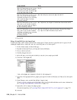
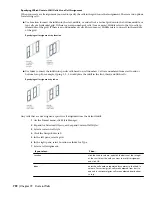
Two profile-based frame examples
NOTE The insertion point of the profile is aligned with the centroid of the frame.
1
Create the profile for the frame.
For information on creating profiles for curtain wall frames, see “
Creating a Profile for a Curtain Wall
Frame
” on page 778.
2
On the Format menu, click Style Manager.
3
Expand Architectural Objects, and expand Curtain Wall Styles.
4
Select a curtain wall style.
5
Click the Design Rules tab.
6
In the left pane, select Frames under Element Definitions.
7
Click New Frame.
8
Enter a descriptive name for the frame.
9
Specify a width and depth for the frame edge.
These dimensions are used to calculate the center point of the edge for aligning the profile and also to
specify a boundary for the adjacent infill.
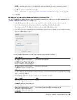
10
Select Use Profile.
NOTE The Profile options are available only if you have profiles in the current drawing.
11
Select a profile from the list.
By default, the profile is inserted using the same width and depth with which it was created.
12
To adjust the size of the profile to fit within the width or depth dimension of the frame edge, select
Auto-Adjust Profile Width or Depth.
13
To mirror the profile, select to mirror along the X or Y axis.
14
To rotate the profile, specify an angle for Rotation.
15
Specify any offsets.
For more information, see “
Specifying Offsets for a Curtain Wall Frame
” on page 779.
16
Click OK.
After you create a frame definition, you can assign it to any frame in a curtain wall. For more information, see “
Assigning
Definitions to Curtain Wall Frames
” on page 793.
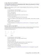
Specifying Offsets for a Curtain Wall Frame
Use this procedure to define the distance that a curtain wall frame is from the floor line, roof line, or baseline. By
default, the outside edges of the frame align with the start and end of the floor line and the start and end of the roof
Defining Curtain Wall Frames | 779
Содержание 00128-051462-9310 - AUTOCAD 2008 COMM UPG FRM 2005 DVD
Страница 1: ...AutoCAD Architecture 2008 User s Guide 2007 ...
Страница 4: ...1 2 3 4 5 6 7 8 9 10 ...
Страница 40: ...xl Contents ...
Страница 41: ...Workflow and User Interface 1 1 ...
Страница 42: ...2 Chapter 1 Workflow and User Interface ...
Страница 146: ...106 Chapter 3 Content Browser ...
Страница 164: ...124 Chapter 4 Creating and Saving Drawings ...
Страница 370: ...330 Chapter 6 Drawing Management ...
Страница 440: ...400 Chapter 8 Drawing Compare ...
Страница 528: ...488 Chapter 10 Display System ...
Страница 540: ...500 Chapter 11 Style Manager ...
Страница 612: ...572 Chapter 13 Content Creation Guidelines ...
Страница 613: ...Conceptual Design 2 573 ...
Страница 614: ...574 Chapter 14 Conceptual Design ...
Страница 678: ...638 Chapter 16 ObjectViewer ...
Страница 683: ...Designing with Architectural Objects 3 643 ...
Страница 684: ...644 Chapter 18 Designing with Architectural Objects ...
Страница 788: ...748 Chapter 18 Walls ...
Страница 942: ...902 Chapter 19 Curtain Walls ...
Страница 1042: ...1002 Chapter 21 AEC Polygons ...
Страница 1052: ...Changing a door width 1012 Chapter 22 Doors ...
Страница 1106: ...Changing a window width 1066 Chapter 23 Windows ...
Страница 1172: ...1132 Chapter 24 Openings ...
Страница 1226: ...Using grips to change the flight width of a spiral stair run 1186 Chapter 25 Stairs ...
Страница 1368: ...Using the Angle grip to edit slab slope 1328 Chapter 28 Slabs and Roof Slabs ...
Страница 1491: ...Design Utilities 4 1451 ...
Страница 1492: ...1452 Chapter 30 Design Utilities ...
Страница 1536: ...1496 Chapter 31 Layout Curves and Grids ...
Страница 1537: ...Grids Grids are AEC objects on which you can anchor other objects such as columns and constrain their locations 32 1497 ...
Страница 1564: ...1524 Chapter 32 Grids ...
Страница 1570: ...Transferring a hatch from one boundary to another Moving a hatch back to original boundary 1530 Chapter 33 Detail Drafting Tools ...
Страница 1611: ...Documentation 5 1571 ...
Страница 1612: ...1572 Chapter 36 Documentation ...
Страница 1706: ...Stretching a surface opening Moving a surface opening 1666 Chapter 36 Spaces ...
Страница 1710: ...Offsetting the edge of a window opening on a freeform space surface 1670 Chapter 36 Spaces ...
Страница 1711: ...Adding a vertex to the edge of a window opening on a freeform space surface Working with Surface Openings 1671 ...
Страница 1712: ...Converting the edge of a window opening to arc on a freeform space surface 1672 Chapter 36 Spaces ...
Страница 1715: ...Removing the vertex of a window opening on a freeform space surface Working with Surface Openings 1675 ...
Страница 1927: ...Elevation Labels Elevation labels are used to dimension height values in plan and section views 41 1887 ...
Страница 1956: ...1916 Chapter 42 Fields ...
Страница 2035: ...Properties of a detail callout The Properties of a Callout Tool 1995 ...
Страница 2060: ...2020 Chapter 45 Callouts ...
Страница 2170: ...2130 Chapter 47 AEC Content and DesignCenter ...
Страница 2171: ...Other Utilities 6 2131 ...
Страница 2172: ...2132 Chapter 48 Other Utilities ...
Страница 2182: ...2142 Chapter 51 Reference AEC Objects ...
Страница 2212: ...2172 Chapter 52 Customizing and Adding New Content for Detail Components ...
Страница 2217: ...AutoCAD Architecture 2008 Menus 54 2177 ...
Страница 2226: ...2186 Chapter 54 AutoCAD Architecture 2008 Menus ...
Страница 2268: ...2228 Index ...