


■
Draw the polylines in plan view. You may want to draw the polylines on top of a wall of the wall style you are
creating the endcaps for. This helps you visualize how the endcap should appear for each component of the wall.
■
Draw each polyline counterclockwise.
■
Ensure that the X value of the start point and the X value of the endpoint of a polyline are the same. If the X values
are different, the endcap will be skewed.
Creating and Applying a Wall Endcap Style Directly in the Drawing
When you create an endcap style and apply it to a wall as described below, you are directly changing the endcap
condition of that wall. You can choose whether the endcap condition is saved either as a new endcap style or modifies
the existing endcap style. When openings, such as doors and windows, exist in a wall to which you apply an endcap,
the end of the wall is trimmed or extended to the endcap without moving the openings.
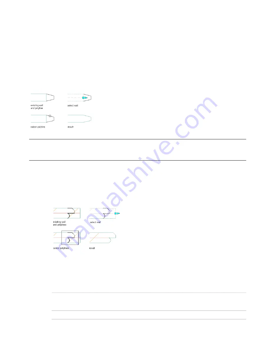
Creating an endcap for a single-component wall
You can use a crossing window to select multiple polylines to create an endcap for a multi-component wall.
NOTE When creating an endcap for multiple component walls that contain components at different elevations, this method
of creating and applying endcaps may not produce the intended results. It is based on the cut plane height of the wall and
does not respond to manual above or below cut plane heights.
Creating a wall endcap style in the drawing
1
In plan view, draw open polylines on top of or near the end of a wall segment to define the shape of the
end condition for each wall component.
The location of the polyline determines how the wall is extended or trimmed when the endcap is added
or modified.
Attaching endcaps to a wall
2
Select the wall, right-click, and click Endcaps
➤
Calculate Automatically.
3
Select the polyline(s) to define the shape of the endcap, and press
ENTER
.
4
Enter y (Yes) to erase the polyline(s), or enter n (No) to keep the polyline(s).
If the current wall endcap style is not the Standard style, you are prompted to modify the current style:
Then …
If you want to …
press ENTER. The selected wall and any other walls in the
drawing that use the wall endcap style are updated with the
new geometry.
modify the wall endcap style that is currently assigned to the
wall
enter n (No).
create a new endcap style from the selected geometry
Creating and Applying a Wall Endcap Style Directly in the Drawing | 739
Содержание 00128-051462-9310 - AUTOCAD 2008 COMM UPG FRM 2005 DVD
Страница 1: ...AutoCAD Architecture 2008 User s Guide 2007 ...
Страница 4: ...1 2 3 4 5 6 7 8 9 10 ...
Страница 40: ...xl Contents ...
Страница 41: ...Workflow and User Interface 1 1 ...
Страница 42: ...2 Chapter 1 Workflow and User Interface ...
Страница 146: ...106 Chapter 3 Content Browser ...
Страница 164: ...124 Chapter 4 Creating and Saving Drawings ...
Страница 370: ...330 Chapter 6 Drawing Management ...
Страница 440: ...400 Chapter 8 Drawing Compare ...
Страница 528: ...488 Chapter 10 Display System ...
Страница 540: ...500 Chapter 11 Style Manager ...
Страница 612: ...572 Chapter 13 Content Creation Guidelines ...
Страница 613: ...Conceptual Design 2 573 ...
Страница 614: ...574 Chapter 14 Conceptual Design ...
Страница 678: ...638 Chapter 16 ObjectViewer ...
Страница 683: ...Designing with Architectural Objects 3 643 ...
Страница 684: ...644 Chapter 18 Designing with Architectural Objects ...
Страница 788: ...748 Chapter 18 Walls ...
Страница 942: ...902 Chapter 19 Curtain Walls ...
Страница 1042: ...1002 Chapter 21 AEC Polygons ...
Страница 1052: ...Changing a door width 1012 Chapter 22 Doors ...
Страница 1106: ...Changing a window width 1066 Chapter 23 Windows ...
Страница 1172: ...1132 Chapter 24 Openings ...
Страница 1226: ...Using grips to change the flight width of a spiral stair run 1186 Chapter 25 Stairs ...
Страница 1368: ...Using the Angle grip to edit slab slope 1328 Chapter 28 Slabs and Roof Slabs ...
Страница 1491: ...Design Utilities 4 1451 ...
Страница 1492: ...1452 Chapter 30 Design Utilities ...
Страница 1536: ...1496 Chapter 31 Layout Curves and Grids ...
Страница 1537: ...Grids Grids are AEC objects on which you can anchor other objects such as columns and constrain their locations 32 1497 ...
Страница 1564: ...1524 Chapter 32 Grids ...
Страница 1570: ...Transferring a hatch from one boundary to another Moving a hatch back to original boundary 1530 Chapter 33 Detail Drafting Tools ...
Страница 1611: ...Documentation 5 1571 ...
Страница 1612: ...1572 Chapter 36 Documentation ...
Страница 1706: ...Stretching a surface opening Moving a surface opening 1666 Chapter 36 Spaces ...
Страница 1710: ...Offsetting the edge of a window opening on a freeform space surface 1670 Chapter 36 Spaces ...
Страница 1711: ...Adding a vertex to the edge of a window opening on a freeform space surface Working with Surface Openings 1671 ...
Страница 1712: ...Converting the edge of a window opening to arc on a freeform space surface 1672 Chapter 36 Spaces ...
Страница 1715: ...Removing the vertex of a window opening on a freeform space surface Working with Surface Openings 1675 ...
Страница 1927: ...Elevation Labels Elevation labels are used to dimension height values in plan and section views 41 1887 ...
Страница 1956: ...1916 Chapter 42 Fields ...
Страница 2035: ...Properties of a detail callout The Properties of a Callout Tool 1995 ...
Страница 2060: ...2020 Chapter 45 Callouts ...
Страница 2170: ...2130 Chapter 47 AEC Content and DesignCenter ...
Страница 2171: ...Other Utilities 6 2131 ...
Страница 2172: ...2132 Chapter 48 Other Utilities ...
Страница 2182: ...2142 Chapter 51 Reference AEC Objects ...
Страница 2212: ...2172 Chapter 52 Customizing and Adding New Content for Detail Components ...
Страница 2217: ...AutoCAD Architecture 2008 Menus 54 2177 ...
Страница 2226: ...2186 Chapter 54 AutoCAD Architecture 2008 Menus ...
Страница 2268: ...2228 Index ...


