


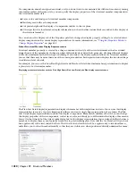


The Plan and Plan High Detail display representations display the previous column using closed polylines. Both
representations display the column geometry, but the Plan High Detail representation is more detailed, including fillets
in the column display. Use the Plan representation to improve performance while modeling, and the Plan High Detail
representation to display an added level of detail for detail drawings.
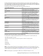
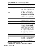
The following table lists the structural member display representations and their uses:
To…
Use this display representation…
display an elevation view of a structural member with simplified
geometry for better performance when modeling.
Elevation
display an elevation view of a structural member in full detail.
Elevation High Detail
display the extruded axis of a structural member and connections
between members. Connections are automatically established
between members when they touch endpoint to endpoint or
endpoint to a point on the extruded axis of another member.
Logical
display a 3D structural member with simplified geometry for better
performance when modeling.
Model
display a 3D structural member in full detail for large scale details.
Model High Detail
display a 2D structural member in less detail than the Plan High Detail
representation to improve performance. Members display as closed
polylines, rather than lines and arcs as in the Plan Low Detail
representation.
Plan
display a 2D structural member in full detail.
Plan High Detail
display a 2D structural member with simple lines and arcs to create
a top view framing plan. Includes a Beam Sketch and Brace Sketch
display component to differentiate beams and braces in plan view.
Plan Low Detail
display a 2D structural member with solid hatching (poche) for plan
view presentation drawings.
Plan Presentation
display a 2D structural member in the screened portion of a screened
floor plan, with components and hatching visibly lighter than some
other objects.
Plan Screened
display a 2D structural member in a reflected ceiling plan.
Reflected
display a 2D structural member in the screened portion of a screened
reflected ceiling plan with components and hatching visibly lighter
than some other objects.
Reflected Screened
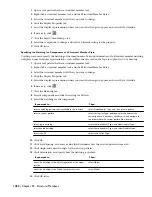
Specifying the Layer, Color, and Linetype of a Structural Member Style
Use this procedure to change the following display properties of the components of a structural member style:
■
Visibility (component is on or off)
■
By material (material assigned to the display component determines its display properties)
■
Layer
■
Color
■
Linetype
■
Lineweight
■
Linetype scale
NOTE If a material assignment determines the display properties of components in the structural member style, you can
change the properties of the display component by clearing By Material. You can also override the material assignment with
a different material. For more information, see
“
Assigning Materials to a Structural Member Style
” on page 1429
.
NOTE For multi-component structural members, hidden lines are calculated one component at a time.
Specifying the Display Properties of a Structural Member Style | 1431
Содержание 00128-051462-9310 - AUTOCAD 2008 COMM UPG FRM 2005 DVD
Страница 1: ...AutoCAD Architecture 2008 User s Guide 2007 ...
Страница 4: ...1 2 3 4 5 6 7 8 9 10 ...
Страница 40: ...xl Contents ...
Страница 41: ...Workflow and User Interface 1 1 ...
Страница 42: ...2 Chapter 1 Workflow and User Interface ...
Страница 146: ...106 Chapter 3 Content Browser ...
Страница 164: ...124 Chapter 4 Creating and Saving Drawings ...
Страница 370: ...330 Chapter 6 Drawing Management ...
Страница 440: ...400 Chapter 8 Drawing Compare ...
Страница 528: ...488 Chapter 10 Display System ...
Страница 540: ...500 Chapter 11 Style Manager ...
Страница 612: ...572 Chapter 13 Content Creation Guidelines ...
Страница 613: ...Conceptual Design 2 573 ...
Страница 614: ...574 Chapter 14 Conceptual Design ...
Страница 678: ...638 Chapter 16 ObjectViewer ...
Страница 683: ...Designing with Architectural Objects 3 643 ...
Страница 684: ...644 Chapter 18 Designing with Architectural Objects ...
Страница 788: ...748 Chapter 18 Walls ...
Страница 942: ...902 Chapter 19 Curtain Walls ...
Страница 1042: ...1002 Chapter 21 AEC Polygons ...
Страница 1052: ...Changing a door width 1012 Chapter 22 Doors ...
Страница 1106: ...Changing a window width 1066 Chapter 23 Windows ...
Страница 1172: ...1132 Chapter 24 Openings ...
Страница 1226: ...Using grips to change the flight width of a spiral stair run 1186 Chapter 25 Stairs ...
Страница 1368: ...Using the Angle grip to edit slab slope 1328 Chapter 28 Slabs and Roof Slabs ...
Страница 1491: ...Design Utilities 4 1451 ...
Страница 1492: ...1452 Chapter 30 Design Utilities ...
Страница 1536: ...1496 Chapter 31 Layout Curves and Grids ...
Страница 1537: ...Grids Grids are AEC objects on which you can anchor other objects such as columns and constrain their locations 32 1497 ...
Страница 1564: ...1524 Chapter 32 Grids ...
Страница 1570: ...Transferring a hatch from one boundary to another Moving a hatch back to original boundary 1530 Chapter 33 Detail Drafting Tools ...
Страница 1611: ...Documentation 5 1571 ...
Страница 1612: ...1572 Chapter 36 Documentation ...
Страница 1706: ...Stretching a surface opening Moving a surface opening 1666 Chapter 36 Spaces ...
Страница 1710: ...Offsetting the edge of a window opening on a freeform space surface 1670 Chapter 36 Spaces ...
Страница 1711: ...Adding a vertex to the edge of a window opening on a freeform space surface Working with Surface Openings 1671 ...
Страница 1712: ...Converting the edge of a window opening to arc on a freeform space surface 1672 Chapter 36 Spaces ...
Страница 1715: ...Removing the vertex of a window opening on a freeform space surface Working with Surface Openings 1675 ...
Страница 1927: ...Elevation Labels Elevation labels are used to dimension height values in plan and section views 41 1887 ...
Страница 1956: ...1916 Chapter 42 Fields ...
Страница 2035: ...Properties of a detail callout The Properties of a Callout Tool 1995 ...
Страница 2060: ...2020 Chapter 45 Callouts ...
Страница 2170: ...2130 Chapter 47 AEC Content and DesignCenter ...
Страница 2171: ...Other Utilities 6 2131 ...
Страница 2172: ...2132 Chapter 48 Other Utilities ...
Страница 2182: ...2142 Chapter 51 Reference AEC Objects ...
Страница 2212: ...2172 Chapter 52 Customizing and Adding New Content for Detail Components ...
Страница 2217: ...AutoCAD Architecture 2008 Menus 54 2177 ...
Страница 2226: ...2186 Chapter 54 AutoCAD Architecture 2008 Menus ...
Страница 2268: ...2228 Index ...