
Working With Elevations
You can create elevations of the building models in your drawings by first drawing an elevation line and mark, and
then creating a 2D or 3D elevation based on that line. You can control the size and shape of any elevation that you
create, and you can update an existing elevation when the objects included in the elevation are modified. 2D elevations
are created with hidden and overlapping lines removed. You can control the appearance of 2D elevations by applying
rules that are controlled by the style and display properties of the 2D elevation.
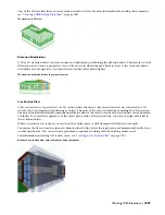
Elevation Line and Marks
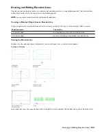
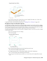
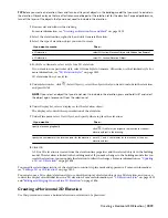
The elevation line defines the extents of the elevation view of your building model. Elevation lines can be straight or
jogged. You can also specify the length and the height of the area defined by the elevation line. Elevation marks, which
typically contain a letter or number and indicate the direction of the elevation, appear at each end of the elevation
line.
After you draw the elevation line, you create an elevation object from the line.
Viewing the elevation line and mark
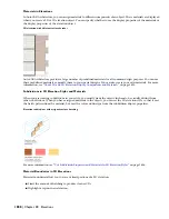
2D Elevations
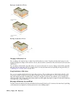
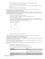
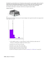
2D elevations are created by drawing an elevation line in front of a number of objects and then creating a 2D elevation
object from them. The elevation object is drawn without hidden and overlapping lines. You can edit a 2D elevation
by changing its object display properties or its style display properties. The 2D elevation style lets you add display
components to the display representation of the elevation and create rules that assign different parts of the elevation
to different display components. You can control the visibility, layer, color, linetype, lineweight, and linetype scale of
each component. You can also assign a material, such as a brick or concrete hatch, to individual components of the
object or the style. Furthermore, you can use linework editing commands to assign individual lines in a 2D elevation
to different display components, and merge geometry into a 2D elevation. You can dimension 2D elevations.
2D building elevation
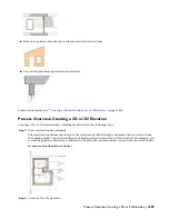
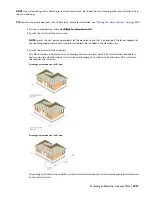
3D Elevations
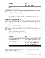
3D elevations are created by drawing an elevation line in front of a number of objects and then creating a 3D isometric
elevation object from them. 3D elevations do not use styles. However, you can control the display of subdivisions
within 3D elevations. Using the Hidden Line Projection command, you can create 2D hidden line projections of any
1806 | Chapter 38 Elevations
Содержание 00128-051462-9310 - AUTOCAD 2008 COMM UPG FRM 2005 DVD
Страница 1: ...AutoCAD Architecture 2008 User s Guide 2007 ...
Страница 4: ...1 2 3 4 5 6 7 8 9 10 ...
Страница 40: ...xl Contents ...
Страница 41: ...Workflow and User Interface 1 1 ...
Страница 42: ...2 Chapter 1 Workflow and User Interface ...
Страница 146: ...106 Chapter 3 Content Browser ...
Страница 164: ...124 Chapter 4 Creating and Saving Drawings ...
Страница 370: ...330 Chapter 6 Drawing Management ...
Страница 440: ...400 Chapter 8 Drawing Compare ...
Страница 528: ...488 Chapter 10 Display System ...
Страница 540: ...500 Chapter 11 Style Manager ...
Страница 612: ...572 Chapter 13 Content Creation Guidelines ...
Страница 613: ...Conceptual Design 2 573 ...
Страница 614: ...574 Chapter 14 Conceptual Design ...
Страница 678: ...638 Chapter 16 ObjectViewer ...
Страница 683: ...Designing with Architectural Objects 3 643 ...
Страница 684: ...644 Chapter 18 Designing with Architectural Objects ...
Страница 788: ...748 Chapter 18 Walls ...
Страница 942: ...902 Chapter 19 Curtain Walls ...
Страница 1042: ...1002 Chapter 21 AEC Polygons ...
Страница 1052: ...Changing a door width 1012 Chapter 22 Doors ...
Страница 1106: ...Changing a window width 1066 Chapter 23 Windows ...
Страница 1172: ...1132 Chapter 24 Openings ...
Страница 1226: ...Using grips to change the flight width of a spiral stair run 1186 Chapter 25 Stairs ...
Страница 1368: ...Using the Angle grip to edit slab slope 1328 Chapter 28 Slabs and Roof Slabs ...
Страница 1491: ...Design Utilities 4 1451 ...
Страница 1492: ...1452 Chapter 30 Design Utilities ...
Страница 1536: ...1496 Chapter 31 Layout Curves and Grids ...
Страница 1537: ...Grids Grids are AEC objects on which you can anchor other objects such as columns and constrain their locations 32 1497 ...
Страница 1564: ...1524 Chapter 32 Grids ...
Страница 1570: ...Transferring a hatch from one boundary to another Moving a hatch back to original boundary 1530 Chapter 33 Detail Drafting Tools ...
Страница 1611: ...Documentation 5 1571 ...
Страница 1612: ...1572 Chapter 36 Documentation ...
Страница 1706: ...Stretching a surface opening Moving a surface opening 1666 Chapter 36 Spaces ...
Страница 1710: ...Offsetting the edge of a window opening on a freeform space surface 1670 Chapter 36 Spaces ...
Страница 1711: ...Adding a vertex to the edge of a window opening on a freeform space surface Working with Surface Openings 1671 ...
Страница 1712: ...Converting the edge of a window opening to arc on a freeform space surface 1672 Chapter 36 Spaces ...
Страница 1715: ...Removing the vertex of a window opening on a freeform space surface Working with Surface Openings 1675 ...
Страница 1927: ...Elevation Labels Elevation labels are used to dimension height values in plan and section views 41 1887 ...
Страница 1956: ...1916 Chapter 42 Fields ...
Страница 2035: ...Properties of a detail callout The Properties of a Callout Tool 1995 ...
Страница 2060: ...2020 Chapter 45 Callouts ...
Страница 2170: ...2130 Chapter 47 AEC Content and DesignCenter ...
Страница 2171: ...Other Utilities 6 2131 ...
Страница 2172: ...2132 Chapter 48 Other Utilities ...
Страница 2182: ...2142 Chapter 51 Reference AEC Objects ...
Страница 2212: ...2172 Chapter 52 Customizing and Adding New Content for Detail Components ...
Страница 2217: ...AutoCAD Architecture 2008 Menus 54 2177 ...
Страница 2226: ...2186 Chapter 54 AutoCAD Architecture 2008 Menus ...
Страница 2268: ...2228 Index ...