


If you are unfamiliar with the display system or layer management, you may want to read more in “
Display System
”
on page 443 and “
Managing Drawing Layers
” on page 404 before specifying the layering and display options.
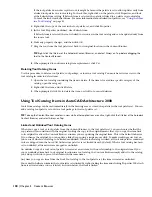
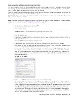
Specifying the Drawing Units
Use this procedure to specify the drawing units in a new or existing drawing. If you change the drawing units, you can
specify whether existing objects in the drawing are scaled to the new units or retain their original size. You can also
specify whether objects inserted from a drawing that uses different units are scaled to the units in the current drawing,
or retain their original size.
You can specify the unit type and precision for linear, angular, area, and volume units. The precision values specify
only the number of decimal places displayed in the interface. They do not determine the number of decimal places
used in the software to make calculations.
When you change the drawing units, the default options under Area and Volume change to reflect the new drawing
units. The drawing scale options on the Scale tab also change to reflect the new drawing units.
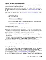
1
In the Drawing Window status bar, click
.
2
Click Drawing Setup.
NOTE Alternatively, you can choose Drawing Setup from the Format menu.
3
Click the Units tab.
4
Under Drawing Units, select the desired units.
Various imperial and metric units are available. The units that you select determine the unit of measurement
that each unit in your drawing represents. For example, if you select Inches, each drawing unit equals one
inch.
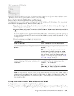
5
To scale objects that you insert into the current drawing from drawings with different drawing units, select
Scale Objects Inserted from Other Drawings.
Clear this option to insert objects at their original size without scaling. For example, if an item that is one
inch long were inserted into a drawing set to millimeters, this setting would scale the item to 25.4 mm in
length when enabled. With this setting disabled, it would remain one unit long, (which would now be
only one millimeter rather than one inch).
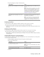
6
Under Length, select a unit type and desired precision.
7
Under Angle, select an angle type and desired precision.
If you want to measure angles clockwise instead of counterclockwise, select Clockwise.
8
Under Base Angle, enter a value for the default 0 angle direction. The default is 0 degrees (East) and a
counter-clockwise direction.
Imported survey drawings may include drafting instructions where changing the base angle might be
desirable to properly orient the data.
The following values match these directions:
Direction
Value
East
0
North
90
West
180
South
270
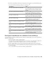
9
Under Area, select an area type and precision.
If you do not want to use the default suffix that is displayed for the drawing units that you specify, enter
a new suffix.
10
Under Volume, select a volume type and precision.
110 | Chapter 4 Creating and Saving Drawings
Содержание 00128-051462-9310 - AUTOCAD 2008 COMM UPG FRM 2005 DVD
Страница 1: ...AutoCAD Architecture 2008 User s Guide 2007 ...
Страница 4: ...1 2 3 4 5 6 7 8 9 10 ...
Страница 40: ...xl Contents ...
Страница 41: ...Workflow and User Interface 1 1 ...
Страница 42: ...2 Chapter 1 Workflow and User Interface ...
Страница 146: ...106 Chapter 3 Content Browser ...
Страница 164: ...124 Chapter 4 Creating and Saving Drawings ...
Страница 370: ...330 Chapter 6 Drawing Management ...
Страница 440: ...400 Chapter 8 Drawing Compare ...
Страница 528: ...488 Chapter 10 Display System ...
Страница 540: ...500 Chapter 11 Style Manager ...
Страница 612: ...572 Chapter 13 Content Creation Guidelines ...
Страница 613: ...Conceptual Design 2 573 ...
Страница 614: ...574 Chapter 14 Conceptual Design ...
Страница 678: ...638 Chapter 16 ObjectViewer ...
Страница 683: ...Designing with Architectural Objects 3 643 ...
Страница 684: ...644 Chapter 18 Designing with Architectural Objects ...
Страница 788: ...748 Chapter 18 Walls ...
Страница 942: ...902 Chapter 19 Curtain Walls ...
Страница 1042: ...1002 Chapter 21 AEC Polygons ...
Страница 1052: ...Changing a door width 1012 Chapter 22 Doors ...
Страница 1106: ...Changing a window width 1066 Chapter 23 Windows ...
Страница 1172: ...1132 Chapter 24 Openings ...
Страница 1226: ...Using grips to change the flight width of a spiral stair run 1186 Chapter 25 Stairs ...
Страница 1368: ...Using the Angle grip to edit slab slope 1328 Chapter 28 Slabs and Roof Slabs ...
Страница 1491: ...Design Utilities 4 1451 ...
Страница 1492: ...1452 Chapter 30 Design Utilities ...
Страница 1536: ...1496 Chapter 31 Layout Curves and Grids ...
Страница 1537: ...Grids Grids are AEC objects on which you can anchor other objects such as columns and constrain their locations 32 1497 ...
Страница 1564: ...1524 Chapter 32 Grids ...
Страница 1570: ...Transferring a hatch from one boundary to another Moving a hatch back to original boundary 1530 Chapter 33 Detail Drafting Tools ...
Страница 1611: ...Documentation 5 1571 ...
Страница 1612: ...1572 Chapter 36 Documentation ...
Страница 1706: ...Stretching a surface opening Moving a surface opening 1666 Chapter 36 Spaces ...
Страница 1710: ...Offsetting the edge of a window opening on a freeform space surface 1670 Chapter 36 Spaces ...
Страница 1711: ...Adding a vertex to the edge of a window opening on a freeform space surface Working with Surface Openings 1671 ...
Страница 1712: ...Converting the edge of a window opening to arc on a freeform space surface 1672 Chapter 36 Spaces ...
Страница 1715: ...Removing the vertex of a window opening on a freeform space surface Working with Surface Openings 1675 ...
Страница 1927: ...Elevation Labels Elevation labels are used to dimension height values in plan and section views 41 1887 ...
Страница 1956: ...1916 Chapter 42 Fields ...
Страница 2035: ...Properties of a detail callout The Properties of a Callout Tool 1995 ...
Страница 2060: ...2020 Chapter 45 Callouts ...
Страница 2170: ...2130 Chapter 47 AEC Content and DesignCenter ...
Страница 2171: ...Other Utilities 6 2131 ...
Страница 2172: ...2132 Chapter 48 Other Utilities ...
Страница 2182: ...2142 Chapter 51 Reference AEC Objects ...
Страница 2212: ...2172 Chapter 52 Customizing and Adding New Content for Detail Components ...
Страница 2217: ...AutoCAD Architecture 2008 Menus 54 2177 ...
Страница 2226: ...2186 Chapter 54 AutoCAD Architecture 2008 Menus ...
Страница 2268: ...2228 Index ...


