


14.1 Fundamental settings
14-7
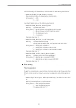
As an initial setting of command unit system (mm/inch), set the following machine data.
• MD20154 EXTERN_GCODE_RESET_VALUE [5]
Meaning: Initial setting of command unit system (mm/inch)
Setting value: 1 --- G20
2 --- G21
As a default Spindle status, set the following machine data.
• MD35020 SPIND_DEFAULT_MODE (Spindle)
Meaning:
Spindle default mode
Setting value: 0 --- Speed reference mode (Without position control)
1 --- Speed reference mode (With position control)
2 --- Positioning axis mode
3 --- C axis mode
Standard setting value: 0
• MD35030 SPIND_DEFAULT_ACT_MASK (Spindle)
Meaning:
Spindle default mode timing
Timing when the default mode, set by MD35020, becomes active.
Setting value: 0 --- When power is turned on.
1 --- When power is turned on and NC starts.
2 --- When power is turned on and reset (M2 and M30).
Standard setting value: 0
• MD35040 SPIND_ACTIVE_AFTER_RESET (Spindle)
Meaning:
Spindle operation after reset and M2/M30.
Setting value: 0 --- Spindle stops on reset and M2/M30.
1 --- Spindle does not stop on reset and M2/M30.
Standard setting value: 0
Drive setting
Fine interpolation
To apply fine interpolation to a speed reference (for interpolation so that the separation from
DP cycle to drive control cycle may be carried out continuously), set the following data to
"1".
• MD3069 digit 1 (Pn127 digit 1) SWITCH_FUNCTION_2 (For each Servo drive axis)
##
Meaning: Fine interpolation of a speed reference.
Setting value: 0 --- Fine interpolation disabled.
1 --- Fine interpolation enabled.
The data must be set to "1".
Summary of Contents for CNC Series
Page 1: ...Maintenance Manual Serviceman Handbook MANUAL No NCSIE SP02 19 Yaskawa Siemens CNC Series...
Page 26: ...Part 1 Hardware...
Page 38: ...System Configuration 1 2 3 Spindle motor designations 1 12...
Page 58: ...Installing the control panels 2 3 5 Installing lightning surge absorbers 2 20...
Page 62: ...Installing the motors 3 4...
Page 84: ...Connection method 4 3 2 Setting the rotary switches on the inverters and servo units 4 22...
Page 96: ...Part 2 Software...
Page 102: ...Software configuration 6 6...
Page 113: ...7 2 Network settings 7 11 8 Click on the radio button to the left of Specify an IP address...
Page 121: ...7 2 Network settings 7 19...
Page 122: ...Part 3 PLC...
Page 154: ...Part 4 Setting up and maintenance...
Page 160: ...Overview of System 10 1 2 Basic operation 10 6...
Page 204: ...How to use Digital Operation 12 2 9 Setting the password setting for write prohibit 12 32...
Page 327: ...Error and Troubleshooting 15 4...
Page 328: ...15 1 Errors without Alarm Display and Troubleshooting 15 5...
Page 329: ...Error and Troubleshooting 15 6...
Page 343: ...Maintenance and Check 16 3 3 Setting up Initializing Absolute encoder 16 14...


