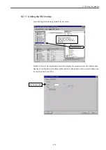


10.2 MD components
10-5
10.2 MD components
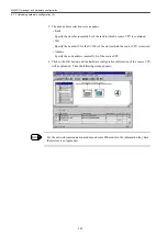
The following diagram shows the drive-related MD and the screen display types.
Schema of 840DI system
YS(840DI)
PLC (MCI board)
・
PLC application
NCK (PCU)
・
NCK application
・
CNC program analysis
・
Interpolation,
Acceleration/Deceleration
・
Position control (CNC-side processing)
・
Backlash, Pitch errors
・
Tool replacement, Data management Machine data
PROFIBUS
I/F
(MCI board)
HMI (PCU)
・
ShopMill screen
・
Standard HMI (Maintenance screen)
・
HMI application
Customer HMI (Exclusive customer screen
)
・
HMI application
Converter(MRXN)
Data bus Data bus
Data bus
Data bus
LatchSinal L
atch signal
Latch signal
Battery supply
Battery supply
Battery supply
Battery supply
Soft ware (0 0)
No parameter
Main soft ware (F0**)
Main soft ware (F***)
Main soft ware (F***)
Main soft
ware
(F***)
Main soft ware (F0**)
Main soft ware (F0**)
Parameter Cn000 1**,2**,4**,5**
Parameter
Pn000 1**,2**,3**
,4**,5**
Parameter Pn000 1**,2**,3**, 4**,5**
Parameter Pn000 1**,2**, 3**,4**,5**
The same as
the left column
The same as
the left column
General
Channel
Axis
Drive parameter
DISPLAY
-MD
Digital operator
General
Channel
MD 10000
19***
(Display screen is single)
MD 20000
29***
(Display screen is single)
Axis
MD 30000
38000
(The display screen has a page(s) per *axis.)
SP
□
X axis
□
Y axis
□
Z axis
□
B axis
□
Spindle inverter
(MXN)
Feed X axis(SGDK)
Feed Y axis
Feed Z/B axis
<1-axis drive><1-axis drive><2-axis drive><1-axis drive>
Drive parameter
(Spindle)
MD 6000 to 8999
(Servo drive)
MD 3000 to 5999
SP
□
X axis
□
Y axis
□
Z axis
□
B axis
□
・
PRM number
→
MD
numbers are changed in alignment
・
The content of setting is
also changed from decimal number (drive side) to
hexadecimal number (NC
side).
W axis
□
W axis
□
Standard setting, Function Enabled/Disabled Mode setting, Compensation Value, Max/Min. Value
setting, and Setting of Gain or Integral Time Constant for the specific function
Content of parameter
・
Mode/Function setting
・
Gain
・
Integral time constant
・
Adjustment of the axis
behavior
・
Toque level
Feed W axis
Type:JUSP-JOP02A
Monitor PRM -> (Un0**)
Function PRM -> (Fn0**)
Monitor PRM -> (Un0**) Function PRM -> (Fn0**)
Monitor PRM -> (Un0**) Function PRM -> (Fn0**)
The same as
the left column
The same as
the left column
Monitor PRM -> (Un0**) Function PRM -> (Fn0**)
Automatically set to the first address 1
Specified with even numbers
Indication/Axis-specific setting/ Content forwarding
Local bus
setting number
↓ ↓ ↓ ↓
"dr-#" indication
NC-side screen
configuration
NC-side screen configuration
"X axis" indication is defined with MD1000. The number in the " " is defined with MD20050.
Local bus setting RSW
Local bus setting RSW
Local bus setting RSW
Profibus setting is defined
through the hard ware
configuration.
Summary of Contents for CNC Series
Page 1: ...Maintenance Manual Serviceman Handbook MANUAL No NCSIE SP02 19 Yaskawa Siemens CNC Series...
Page 26: ...Part 1 Hardware...
Page 38: ...System Configuration 1 2 3 Spindle motor designations 1 12...
Page 58: ...Installing the control panels 2 3 5 Installing lightning surge absorbers 2 20...
Page 62: ...Installing the motors 3 4...
Page 84: ...Connection method 4 3 2 Setting the rotary switches on the inverters and servo units 4 22...
Page 96: ...Part 2 Software...
Page 102: ...Software configuration 6 6...
Page 113: ...7 2 Network settings 7 11 8 Click on the radio button to the left of Specify an IP address...
Page 121: ...7 2 Network settings 7 19...
Page 122: ...Part 3 PLC...
Page 154: ...Part 4 Setting up and maintenance...
Page 160: ...Overview of System 10 1 2 Basic operation 10 6...
Page 204: ...How to use Digital Operation 12 2 9 Setting the password setting for write prohibit 12 32...
Page 327: ...Error and Troubleshooting 15 4...
Page 328: ...15 1 Errors without Alarm Display and Troubleshooting 15 5...
Page 329: ...Error and Troubleshooting 15 6...
Page 343: ...Maintenance and Check 16 3 3 Setting up Initializing Absolute encoder 16 14...


