


16.4 Analogue monitor
16-13
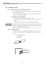
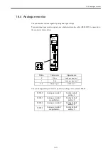
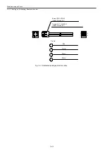
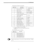
The following monitor signals can be monitored.
∗ 1.
Torque reference after gravity compensation (Pn411)
∗ 2.
In the case of speed control, the monitor signal for position deviation
is indefinite.
Monitor magnification can be set as follows:
Analogue monitor output voltage is
±
8 V max. Even if the voltage exceeds this range, it is displayed
as
±
8 V.
Pn003.0 and
Pn003.2 settings
Descriptions
Monitor signal
Observation gain
0
Motor rotation speed
1V/1000 min
-1
1
Speed reference
1V/1000 min
-1
2
Torque reference
*1
1V/100% Rated torque
3
Position deviation
*2
0.05V/a Command unit
4
Position amplitude deviation
*2
(Position control compensator deviation)
0.05V/a Command unit
5
Position command speed
[min
-1
conversion]
1V/1000 min
-1
6
Observer speed
1V/1000 min
-1
7
Collision detection amount
1V/100
%
8
Quadrant error compensation
1V/100
%
9
Speed feed forward
1V/1000 min
-1
A
Torque feed forward
1V/100
%
B
Model torque reference
1V/100
%
C
Model position deviation
0.05V/a command unit
D
Estimated disturbance torque
1V/100
%
E
Vibration-damping monitor
1V/1000 min
-1
F
System constant data-setting output
-
Pn003.1 and
Pn003.3 settings
Descriptions
0
Monitor magnification: 1
1
Monitor magnification: 10
2
Monitor magnification: 100
3
Monitor magnification: 1/10
4
Monitor magnification: 1/100
INFO
Summary of Contents for CNC Series
Page 1: ...Maintenance Manual Serviceman Handbook MANUAL No NCSIE SP02 19 Yaskawa Siemens CNC Series...
Page 26: ...Part 1 Hardware...
Page 38: ...System Configuration 1 2 3 Spindle motor designations 1 12...
Page 58: ...Installing the control panels 2 3 5 Installing lightning surge absorbers 2 20...
Page 62: ...Installing the motors 3 4...
Page 84: ...Connection method 4 3 2 Setting the rotary switches on the inverters and servo units 4 22...
Page 96: ...Part 2 Software...
Page 102: ...Software configuration 6 6...
Page 113: ...7 2 Network settings 7 11 8 Click on the radio button to the left of Specify an IP address...
Page 121: ...7 2 Network settings 7 19...
Page 122: ...Part 3 PLC...
Page 154: ...Part 4 Setting up and maintenance...
Page 160: ...Overview of System 10 1 2 Basic operation 10 6...
Page 204: ...How to use Digital Operation 12 2 9 Setting the password setting for write prohibit 12 32...
Page 327: ...Error and Troubleshooting 15 4...
Page 328: ...15 1 Errors without Alarm Display and Troubleshooting 15 5...
Page 329: ...Error and Troubleshooting 15 6...
Page 343: ...Maintenance and Check 16 3 3 Setting up Initializing Absolute encoder 16 14...


