


How to use Digital Operation
12.2.1 Alarm Trace Back Mode
12-18
12.2.1 Alarm Trace Back Mode
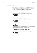
On the alarm trace back mode, you can view the latest alarms up to ten so that you may
check what kind of alarms have occurred.
The alarm trace back data can not be cleared when the alarm reset is initiated or even when
the SERVOPACK power supply is cut off. This has no effect on the operation.
You can delete these data using the clear on the alarm trace back mode of the special mode.
See the section 12.2.2.
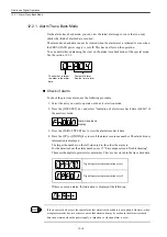
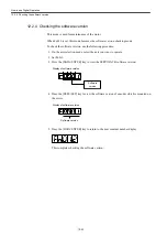
Check of alarm
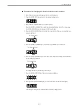
To check the previous alarm, use the following procedure.
1. Select the axis you want to operate on the axis selection mode.
2. Press the [DSPL/SET] key and select "Indication of alarm trace back data (Fn000)" of
the auxiliary mode.
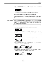
3. Press the [DATA/ENTER] key to view the alarm trace back data.
4. Press the [UP] or [DOWN] key to scroll the alarm occurence number. The alarm history
information is displayed.
The larger the number on the left-side digit is, the older the alarm is.
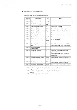
For the details about the alarm number, see 15 "Error diagnosis and Troubleshooting".
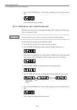
These are the digital operator relevant alarms. They are not stored in the trace back data.
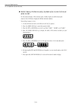
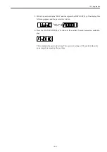
If there occurs no alarm, the indication is displayed like following.
If there successively occurs the same alarm, that alarm trace back data is not updated. However, when
a single alarm code has two or more causes, that alarm code may be written in the alarm trace back
data in succession when the power supply is turned on or when an alarm is reset.
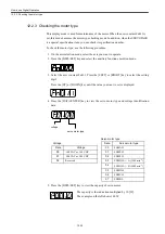
Digital operator communication error 1
Digital operator communication error 2
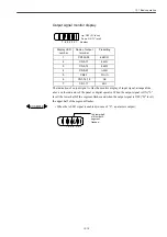
Content of alarm.
See the list of alarm.
The number is larger,
the older is the alarm
data.
Alarm trace back
display
INFO
Summary of Contents for CNC Series
Page 1: ...Maintenance Manual Serviceman Handbook MANUAL No NCSIE SP02 19 Yaskawa Siemens CNC Series...
Page 26: ...Part 1 Hardware...
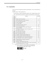
Page 38: ...System Configuration 1 2 3 Spindle motor designations 1 12...
Page 58: ...Installing the control panels 2 3 5 Installing lightning surge absorbers 2 20...
Page 62: ...Installing the motors 3 4...
Page 84: ...Connection method 4 3 2 Setting the rotary switches on the inverters and servo units 4 22...
Page 96: ...Part 2 Software...
Page 102: ...Software configuration 6 6...
Page 113: ...7 2 Network settings 7 11 8 Click on the radio button to the left of Specify an IP address...
Page 121: ...7 2 Network settings 7 19...
Page 122: ...Part 3 PLC...
Page 154: ...Part 4 Setting up and maintenance...
Page 160: ...Overview of System 10 1 2 Basic operation 10 6...
Page 204: ...How to use Digital Operation 12 2 9 Setting the password setting for write prohibit 12 32...
Page 327: ...Error and Troubleshooting 15 4...
Page 328: ...15 1 Errors without Alarm Display and Troubleshooting 15 5...
Page 329: ...Error and Troubleshooting 15 6...
Page 343: ...Maintenance and Check 16 3 3 Setting up Initializing Absolute encoder 16 14...


