


Drive set-up procedure
14.1.2 NCK processing capability
14-6
14.1.2 NCK processing capability
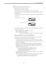
With this setting, it is specified that how much CPU power should be distributed from PCU
unit to NCK (NC kernel) in YS 840DI system.
50-75% should be specified with the following machine data.
• MD10185 NCK_PCOS_TIME_RATIO
Meaning: CPU power ratio to be distributed to NCK.
Setting value: [%]
Standard setting value: 65 [%]
Set the following machine data to make an adjustment between high NCK processing speed
and high screen refreshing speed.
• MD10131 SUPPRESS_SCREEN_REFRESH
Meaning: Suppression setting of HMI screen refreshing
0 --- Suppression for entire system
1 --- Suppression only for a partial system in which the processing must be
done in a short time.
2 --- No suppression at all
Standard setting value: 0
14.1.3 Servo control method and fundamental operation
CNC setting
The servo control method of YS 840DI system is called "DSC" (Direct Servo Control). In
this method, CNC and drives perform position control to attain high-speed response. To
enable this control method, set the following parameters.
• MC32640 STIFFNESS_CONTROL_ENABLE [0] (for each axis) ##
Setting value: 1
• MD13060 DRIVE_TELEEGRAM_TYPE [0] (for the 1st axis) ##
MD13060 DRIVE_TELEEGRAM_TYPE [1] (for the 1st axis) ##
: (Repeat for all remaining axes)
Setting value: 201
For operation specification at NCK reset and system shutdown, set the following machine
data.
• MD11250 PROFIBUS_SHUTDOWN_TYPE (Spindle)
Meaning: Operation specification at NCK reset and shutdown
Setting value: 0 --- Drive stops on an alarm without PROFIBUS cleared.
1 --- Drive stops after deceleration with PROFIBUS cleared.
2 --- Drive stops after deceleration without PROFIBUS cleared.
Standard setting value: 2
This machine data was added to 01.00.00 system. For systems earlier than this version, the
data should be set to 0.
INFO
Summary of Contents for CNC Series
Page 1: ...Maintenance Manual Serviceman Handbook MANUAL No NCSIE SP02 19 Yaskawa Siemens CNC Series...
Page 26: ...Part 1 Hardware...
Page 38: ...System Configuration 1 2 3 Spindle motor designations 1 12...
Page 58: ...Installing the control panels 2 3 5 Installing lightning surge absorbers 2 20...
Page 62: ...Installing the motors 3 4...
Page 84: ...Connection method 4 3 2 Setting the rotary switches on the inverters and servo units 4 22...
Page 96: ...Part 2 Software...
Page 102: ...Software configuration 6 6...
Page 113: ...7 2 Network settings 7 11 8 Click on the radio button to the left of Specify an IP address...
Page 121: ...7 2 Network settings 7 19...
Page 122: ...Part 3 PLC...
Page 154: ...Part 4 Setting up and maintenance...
Page 160: ...Overview of System 10 1 2 Basic operation 10 6...
Page 204: ...How to use Digital Operation 12 2 9 Setting the password setting for write prohibit 12 32...
Page 327: ...Error and Troubleshooting 15 4...
Page 328: ...15 1 Errors without Alarm Display and Troubleshooting 15 5...
Page 329: ...Error and Troubleshooting 15 6...
Page 343: ...Maintenance and Check 16 3 3 Setting up Initializing Absolute encoder 16 14...


