


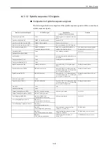
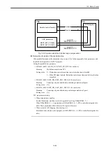


Drive set-up procedure
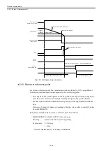
14.3.9 Absolute value detection
14-78
14.3.9 Absolute value detection
For machine data setting for the absolute value encoder, see Section 14.1.5 Motor Encoder
and Section 14.1.6 Separately Mounted Encoder.
Other primary CNC data required for absolute value detection function are listed below.
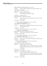
• MD34090 ENC_MOVE_DIST_CORR [0] (For each axis)
Meaning:
Origin position offset (motor encoder)
Setting value: [mm] or [deg]
Note: When absolute value detection function is enabled, the origin setting
value is written into this parameter.
• MD34090 ENC_MOVE_DIST_CORR [1] (For each axis)
Meaning:
Origin position offset (separately mounted encoder)
Setting value:
[mm] or [deg]
Note: When absolute value detection function is enabled, the origin setting
value is written into this parameter.
• MD34100 REFP_SET_POS [0] (For each axis)
Meaning:
After return to reference point, coordinate system offset
(motor encoder)
Setting value: [mm] or [deg]
• MD34100 REFP_SET_POS [1] (For each axis)
Meaning:
After return to reference point, coordinate system offset
(separately mounted encoder)
Setting value: [mm] or [deg]
• MD34200 ENC_REFP_MODE [0] (For each axis)
Meaning:
Return to reference point mode setting (motor encoder)
Setting value: 0---No origin pulse
1---C phase return to reference point
Note: When the absolute value detection function is enabled, you must
specify "0".
• MD34200 ENC_REFP_MODE [1] (For each axis)
Meaning:
Return to reference point mode setting (separately mounted encoder)
Setting value: 0---No origin pulse
1---C phase return to reference point
Note: When the absolute value detection function is enabled, you must
specify "0".
Summary of Contents for CNC Series
Page 1: ...Maintenance Manual Serviceman Handbook MANUAL No NCSIE SP02 19 Yaskawa Siemens CNC Series...
Page 26: ...Part 1 Hardware...
Page 38: ...System Configuration 1 2 3 Spindle motor designations 1 12...
Page 58: ...Installing the control panels 2 3 5 Installing lightning surge absorbers 2 20...
Page 62: ...Installing the motors 3 4...
Page 84: ...Connection method 4 3 2 Setting the rotary switches on the inverters and servo units 4 22...
Page 96: ...Part 2 Software...
Page 102: ...Software configuration 6 6...
Page 113: ...7 2 Network settings 7 11 8 Click on the radio button to the left of Specify an IP address...
Page 121: ...7 2 Network settings 7 19...
Page 122: ...Part 3 PLC...
Page 154: ...Part 4 Setting up and maintenance...
Page 160: ...Overview of System 10 1 2 Basic operation 10 6...
Page 204: ...How to use Digital Operation 12 2 9 Setting the password setting for write prohibit 12 32...
Page 327: ...Error and Troubleshooting 15 4...
Page 328: ...15 1 Errors without Alarm Display and Troubleshooting 15 5...
Page 329: ...Error and Troubleshooting 15 6...
Page 343: ...Maintenance and Check 16 3 3 Setting up Initializing Absolute encoder 16 14...


