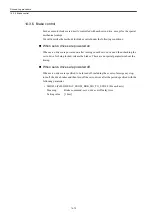


Drive set-up procedure
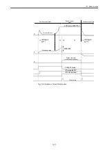
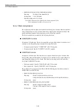
14.3.11 Collision detection
14-84
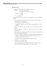
• MD3067 (Pn125) INERTIA_ADJ_DISTURB_OBSRVR (For each servo axis)
Meaning:
Disturbance observer inertia compensation
Setting value: [%]
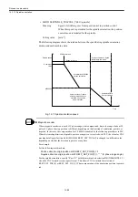
• MD3368 (Pn412) DISTURB_TORQUE_LEVEL_1 (For each servo axis)
Meaning:
1st torque disturbance level
Disturbance level for feed except for positioning feed
Setting value: [%]
• MD3369 (Pn413) DISTURB_TORQUE_LEVEL_2 (For each servo axis)
Meaning:
2nd torque disturbance level
Disturbance level for positioning feed
Setting value: [%]
• MD3370 (Pn414) DISTURB_TORQUE_LEVEL_3 (For each servo axis)
Meaning:
3rd torque disturbance level
Disturbance level for forced entry
Setting value: [%]
• MD3371 (Pn415) DISTURB_TORQUE_LEVEL_4 (For each servo axis)
Meaning:
4th torque disturbance level
When Collision Detection is disabled
Setting value: [%]
Note: Be sure to set the parameter to "0".
• MD3372 (Pn416) COMPLIANCE_TORQUE (For each servo axis)
Meaning:
Compliance torque
Setting value: [%]
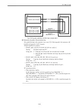
Relevant I/O
• DB3nDBX20. 2 (Torque limit 2) (For each servo axis)
Meaning:
Collision detection function enabled/disabled
By setting this signal to "1", the collision detection signal is enabled.
Setting value: 0---collision detection function disabled
1---collision detection function enabled
• DB3nDBX21. 2 (Drive parameter set selection d2) (For each servo axis)
Meaning:
Collision detection function forced input selection
Setting value: 0---forced input disturbance level disabled
1---forced input disturbance level enabled
• DB3nDBX93. 2 (Active drive parameter set d2) (per servo axis)
Meaning:
Collision detection function forced input selection state
Setting value: 0---forced input disturbance level not selected
1---forced input disturbance level selected
Summary of Contents for CNC Series
Page 1: ...Maintenance Manual Serviceman Handbook MANUAL No NCSIE SP02 19 Yaskawa Siemens CNC Series...
Page 26: ...Part 1 Hardware...
Page 38: ...System Configuration 1 2 3 Spindle motor designations 1 12...
Page 58: ...Installing the control panels 2 3 5 Installing lightning surge absorbers 2 20...
Page 62: ...Installing the motors 3 4...
Page 84: ...Connection method 4 3 2 Setting the rotary switches on the inverters and servo units 4 22...
Page 96: ...Part 2 Software...
Page 102: ...Software configuration 6 6...
Page 113: ...7 2 Network settings 7 11 8 Click on the radio button to the left of Specify an IP address...
Page 121: ...7 2 Network settings 7 19...
Page 122: ...Part 3 PLC...
Page 154: ...Part 4 Setting up and maintenance...
Page 160: ...Overview of System 10 1 2 Basic operation 10 6...
Page 204: ...How to use Digital Operation 12 2 9 Setting the password setting for write prohibit 12 32...
Page 327: ...Error and Troubleshooting 15 4...
Page 328: ...15 1 Errors without Alarm Display and Troubleshooting 15 5...
Page 329: ...Error and Troubleshooting 15 6...
Page 343: ...Maintenance and Check 16 3 3 Setting up Initializing Absolute encoder 16 14...


