Table of Contents
v
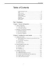
Table of Contents
Safety-related symbol marks.........................................................................iii
Icons............................................................................................................. iv
Table of Contents .......................................................................................... v
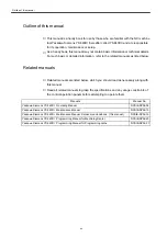
Outline of this manual...................................................................................xii
Related manuals ..........................................................................................xii
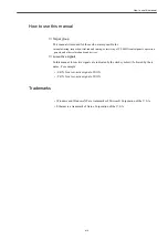
How to use this manual ...............................................................................xiii
Trademarks .................................................................................................xiii
Safety precautions.......................................................................................xiv
Warning labels...........................................................................................xxiv
Part 1 Hardware
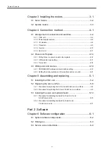
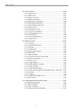
Chapter 1 System Configuration ....................................1-1
1.1 System configuration...................................................................1-2
1.1.1 General wiring drawing...............................................................................1-2
1.1.2 List of system components .........................................................................1-4
1.2 Meanings of component designations.........................................1-8
1.2.1 SERVOPACK designations ........................................................................1-8
1.2.2 Servo motor designations.........................................................................1-10
1.2.3 Spindle motor designations ...................................................................... 1-11
Chapter 2 Installing the control panels...........................2-1
2.1 Designing the panels...................................................................2-2
2.1.1 Environmental conditions for installing the control panels and other sy
stem components .......................................................................................2-2
2.1.2 Thermal design of the enclosures ..............................................................2-3
2.1.3 Heat dissipation ..........................................................................................2-6
2.1.4 Power consumption ....................................................................................2-8
2.2 Protecting against electric noise..................................................2-9
2.2.1 Separation of cables...................................................................................2-9
2.2.2 Noise-proof devices..................................................................................2-10
2.2.3 Grounding.................................................................................................2-12
2.2.4 Cable shield clamp ...................................................................................2-13
2.3 Installation precautions..............................................................2-14
2.3.1 Installing the CNC units ............................................................................2-14
2.3.2 Installing the feed/spindle SERVOPACK..................................................2-15
2.3.3 Orientation of and installation space for the SERVOPACK ......................2-16
2.3.4 Installation space for the I/O modules ......................................................2-17
2.3.5 Installing lightning-surge absorbers..........................................................2-18
Summary of Contents for CNC Series
Page 1: ...Maintenance Manual Serviceman Handbook MANUAL No NCSIE SP02 19 Yaskawa Siemens CNC Series...
Page 26: ...Part 1 Hardware...
Page 38: ...System Configuration 1 2 3 Spindle motor designations 1 12...
Page 58: ...Installing the control panels 2 3 5 Installing lightning surge absorbers 2 20...
Page 62: ...Installing the motors 3 4...
Page 84: ...Connection method 4 3 2 Setting the rotary switches on the inverters and servo units 4 22...
Page 96: ...Part 2 Software...
Page 102: ...Software configuration 6 6...
Page 113: ...7 2 Network settings 7 11 8 Click on the radio button to the left of Specify an IP address...
Page 121: ...7 2 Network settings 7 19...
Page 122: ...Part 3 PLC...
Page 154: ...Part 4 Setting up and maintenance...
Page 160: ...Overview of System 10 1 2 Basic operation 10 6...
Page 204: ...How to use Digital Operation 12 2 9 Setting the password setting for write prohibit 12 32...
Page 327: ...Error and Troubleshooting 15 4...
Page 328: ...15 1 Errors without Alarm Display and Troubleshooting 15 5...
Page 329: ...Error and Troubleshooting 15 6...
Page 343: ...Maintenance and Check 16 3 3 Setting up Initializing Absolute encoder 16 14...


