
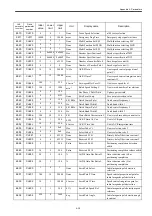
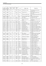

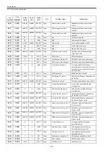
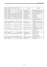


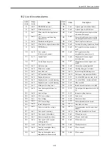
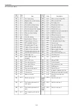


Drive data list
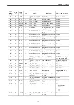
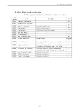
B.4 List of Inverter monitor data
A-28
B.4 List of Inverter monitor data
The following monitor data have been confirmed with a digital operator for drives
.
UN
number
Item
Description
Unit
Un001
Speed feedback
min
-1
Un002
Speed reference
min
-1
Un003
Reserved
Un004
Torque reference
Short-time duration rated torque
%
Un005
Reserved
Un006
Inverter output current
A
Un007
Output frequency
Hz
Un008
Internal status of the sequence
[4]
[3]
[2]
[1] [0]
RUN2
RUN1 RUN JOG1 ACCDECDY
ACCDEC IRDY ACC
−
−
−
−
−
−
−
RUN2 /* At operation */
RUN1 /* Operation command */
RUN /* Operation command */
JOG1 /* JOG command */
ACCDECDY /* At acceleration/deceleration */
ACCDEC /* At acceleration/deceleration */
IRDY
/* Inverter ready */
ACC
/* At acceleration */
Un009
External input signals
[4] [3] [2] [1] [0]
RDY EMG FOR REV TLH
TLL SC
−
CHW PPI
ORT LGR MGR CAX
−
RDY
/* At operation preparation */
EMG
/* Emergency stop */
FOR
/* Forward rotation */
REV
/* Reverse rotation */
TLH
/* Torque limit H */
TLL
/* Torque limit L */
SC
/* Soft start cancelled */
CHW
/* Winding switch-over ON: Low-
speed winding*/
PPI
/* Speed controlling PP1 switch-over
ON: PI*/
ORT
/* Orientation */
LGR
/* L gear selection */
MGR
/* M gear selection */
CAX
/* C-axis switch-over */
Un010
External output signals
[4] [3] [2] [1] [0]
ZSPD AGR SDET TDET TLE
ORGSIG OREND CHWEND FLTSIG TALM
−
−
−
−
CAXCMP
ZSPD /* Zero speed */
AGR /* Speed matching */
SDET /* Speed detection */
TDET /* Torque detection */
TLE /* At torque limit */
ORGSIG /* Load-axis zero point */
OREND /* Orientation completed */
CHWEND /* Winding switch-over completed ON:
Low-speed winding*/
FLTSIG /* Failure */
TALM /* Error warning */
CAXCMP /* C-axis switch-over completed */
Un011
Inverter capacity
kW
Un012
Motor temperature
℃
Un013
Heat sink temperature
℃
Un014
Direct-current voltage of the bus
V
Summary of Contents for CNC Series
Page 1: ...Maintenance Manual Serviceman Handbook MANUAL No NCSIE SP02 19 Yaskawa Siemens CNC Series...
Page 26: ...Part 1 Hardware...
Page 38: ...System Configuration 1 2 3 Spindle motor designations 1 12...
Page 58: ...Installing the control panels 2 3 5 Installing lightning surge absorbers 2 20...
Page 62: ...Installing the motors 3 4...
Page 84: ...Connection method 4 3 2 Setting the rotary switches on the inverters and servo units 4 22...
Page 96: ...Part 2 Software...
Page 102: ...Software configuration 6 6...
Page 113: ...7 2 Network settings 7 11 8 Click on the radio button to the left of Specify an IP address...
Page 121: ...7 2 Network settings 7 19...
Page 122: ...Part 3 PLC...
Page 154: ...Part 4 Setting up and maintenance...
Page 160: ...Overview of System 10 1 2 Basic operation 10 6...
Page 204: ...How to use Digital Operation 12 2 9 Setting the password setting for write prohibit 12 32...
Page 327: ...Error and Troubleshooting 15 4...
Page 328: ...15 1 Errors without Alarm Display and Troubleshooting 15 5...
Page 329: ...Error and Troubleshooting 15 6...
Page 343: ...Maintenance and Check 16 3 3 Setting up Initializing Absolute encoder 16 14...


