


Drive set-up procedure
14.2.4 Backlash compensation
14-40
14.2.4 Backlash compensation
In YS 840DI system, backlash compensation is carried out at CNC. The following explains
how to set backlash-related machine data.
• MD32450 BACKLASH [0] (For each axis)
Meaning:
Backlash compensation amount
Setting value: [mm]
Note: For variable-speed backlash
compensation
function, refer to sepa-
rate specifications.
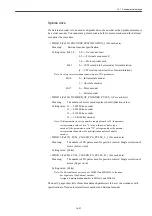
14.2.5 Quadrant error compensation
In YS 840DI system, functional quadrant error compensation function is used as a quadrant
error compensation function for Servo axis.
The quadrant error compensation is carried out at a drive. (The compensation function in the
CNC cannot be used.)
The following shows parameters relating to this function.
For detailed procedures to adjust functional quadrant error compensation function, refer to a
separate instruction manual.
• MD3068 digit 1 (Pn126 digit 1) SWITCH_FUNCTION_1 (For each axis)
Meaning:
Selection of functional quadrant error compensation function
Setting value: 0 --- Disabled
1 --- Enabled (Without pulse suppression processing)
2 --- Enabled (With pulse suppression processing)
Note: Be sure to set the parameter to "2".
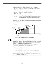
• MD3101 (Pn147) 1ST_P_GAIN_QUAD_ERR_COMP (For each axis)
Meaning:
Quadrant error compensation 1st-stage gain (Negative -> Positive)
Setting value: [0.00001/s
3
]
Equivalent to the quadrant error compensation 1st-stage integration time
constant for J300/J100 system.
For relations with previous parameters, refer to the (INFO) mentioned
later.
• MD3102 (Pn148) 1ST_P_LMT_OFS_QUAD_ERR_COM (For each axis)
Meaning:
Quadrant error compensation 1st-stage limit offset (Negative -> Positive)
Setting value: [0.01%]
Summary of Contents for CNC Series
Page 1: ...Maintenance Manual Serviceman Handbook MANUAL No NCSIE SP02 19 Yaskawa Siemens CNC Series...
Page 26: ...Part 1 Hardware...
Page 38: ...System Configuration 1 2 3 Spindle motor designations 1 12...
Page 58: ...Installing the control panels 2 3 5 Installing lightning surge absorbers 2 20...
Page 62: ...Installing the motors 3 4...
Page 84: ...Connection method 4 3 2 Setting the rotary switches on the inverters and servo units 4 22...
Page 96: ...Part 2 Software...
Page 102: ...Software configuration 6 6...
Page 113: ...7 2 Network settings 7 11 8 Click on the radio button to the left of Specify an IP address...
Page 121: ...7 2 Network settings 7 19...
Page 122: ...Part 3 PLC...
Page 154: ...Part 4 Setting up and maintenance...
Page 160: ...Overview of System 10 1 2 Basic operation 10 6...
Page 204: ...How to use Digital Operation 12 2 9 Setting the password setting for write prohibit 12 32...
Page 327: ...Error and Troubleshooting 15 4...
Page 328: ...15 1 Errors without Alarm Display and Troubleshooting 15 5...
Page 329: ...Error and Troubleshooting 15 6...
Page 343: ...Maintenance and Check 16 3 3 Setting up Initializing Absolute encoder 16 14...


